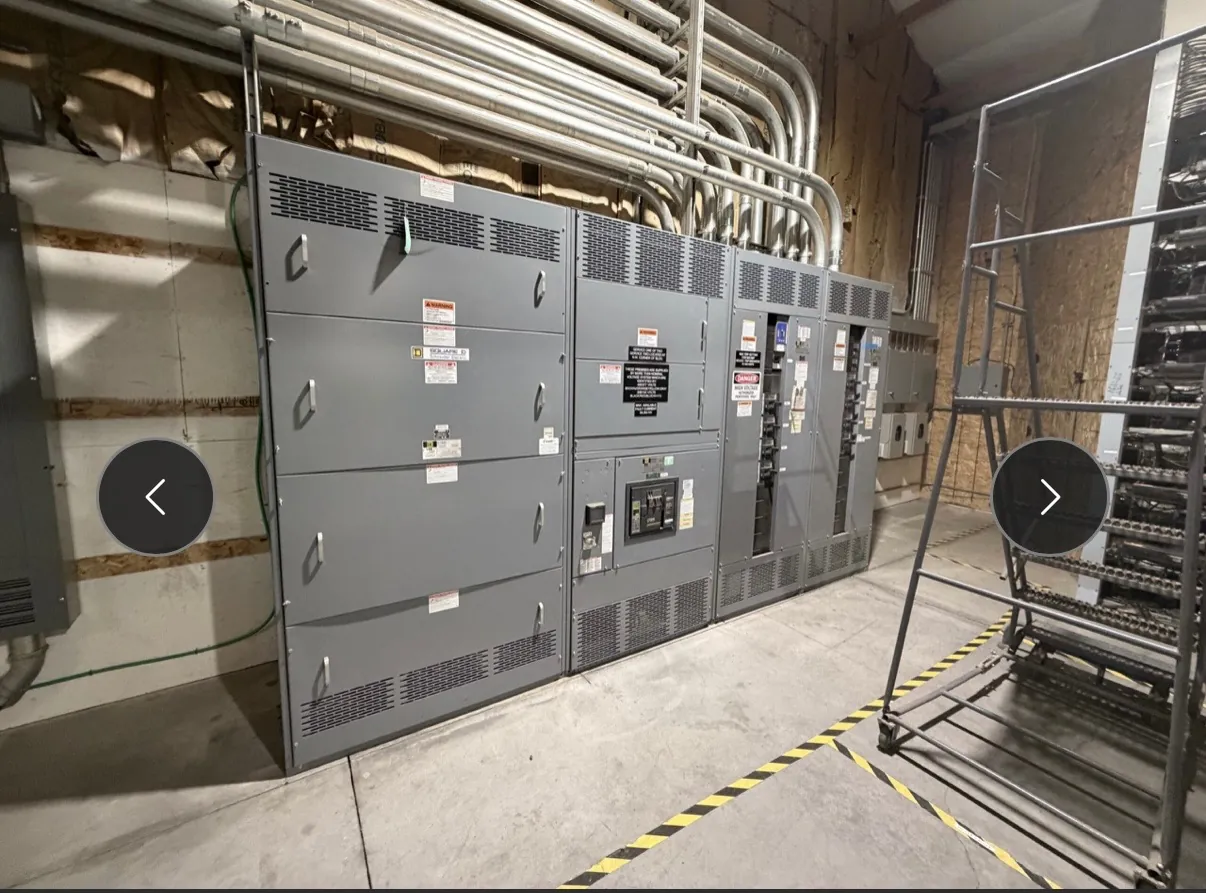
Metal-Clad Switchgear for Las Vegas Facilities
Metal-clad switchgear is a medium-voltage assembly built around separately enclosed functional compartments. For a Las Vegas project, its design begins with the electrical service and the facility’s operating needs—not simply a nominal voltage or a preferred lineup length. The main bus, incoming section, feeder sections, protective devices, metering interfaces and available space must work together as a system. A U.S. manufacturer can build new custom equipment with all-American components and ship it to Nevada; project-specific suitability still depends on engineering review of the site and utility requirements.
Compartmentalization helps define where the bus, circuit breakers, instrument transformers, control wiring and cable terminations are located. The barriers and access arrangements affect inspection, maintenance planning and the consequences of a fault within a compartment. Those features must be evaluated for the specified assembly and application rather than treated as a substitute for system coordination or an assurance of risk-free operation. The project team should identify the applicable construction and accessibility expectations early, including any constraints imposed by the electrical room.
IEEE C37.20.2 and the Specified Assembly
IEEE C37.20.2 is the relevant standard to identify when specifying metal-clad switchgear. The project specification should state the applicable edition and requirements, then confirm that the proposed equipment configuration and ratings meet the project’s needs. Referencing the standard alone does not establish that a particular lineup is listed, approved by a utility, or suitable for every installation. Applicable standards, product documentation and any requested listing or certification must be confirmed for the exact equipment being quoted.
Engineers should distinguish equipment ratings from the operating voltage of the power system. Voltage class, continuous current, interrupting capability, short-time withstand and insulation requirements are separate design inputs; the appropriate values depend on the available system data and the installation. Do not select a switchgear rating from a facility’s service voltage alone. The engineer of record should verify the design against the utility information, fault-current study, protection scheme and site conditions.
Withdrawable Breakers, Bus Arrangement and Interfaces
Withdrawable breakers are designed to move between defined connected, test and disconnected positions within their compartments. That arrangement can support maintenance and operational planning, but it also affects lineup depth, compartment geometry, control connections and the procedures established by the facility. The specification should identify breaker type, required positions, electrical and mechanical interlocks, auxiliary contacts, control power and any remote indication or control interfaces. Compatibility among breakers, cubicles and controls must be confirmed as a complete design.
Bus configuration is another consequential choice. Main-tie-main, single-bus or other arrangements can affect continuity options, protection logic, operating complexity, space and cost. The appropriate topology depends on the facility’s load priorities and approved operating philosophy; additional switching flexibility is not automatically the best choice. Confirm cable entry direction, termination space, conduit or trench locations, access clearances, room layout and future feeder needs before finalizing the lineup. Las Vegas delivery planning should also account for the receiving route, unloading arrangements and any building access limits, without assuming a particular site can accommodate a given shipping section.
Grounding, Relays and Protection Coordination
Grounding requirements depend on the system configuration, including how the source is grounded and how ground faults are detected and cleared. The engineer should define the grounding method, ground bus and bonding interfaces, cable shield or ground connections, and any neutral or grounding-transformer arrangements that apply. These details influence protection settings and must be coordinated with upstream and downstream equipment. A general equipment description cannot determine the correct grounding scheme for a specific facility.
Relay selection and coordination should follow the project’s protection study. Inputs may include source fault information, transformer data, feeder characteristics, load profiles, motor starting requirements and downstream protective-device curves. Relays, current transformers and voltage transformers must have suitable characteristics and be assigned functions consistent with the design. Confirm trip and close circuits, control-power source, communications protocol, alarm points and interface responsibilities across switchgear, transformers, generators or building controls. Final settings require qualified engineering review; they should not be inferred from a quotation description.
Las Vegas Service and Utility Metering Requirements
Before sizing the main section, confirm the service characteristics and utility metering requirements with the serving utility and project engineer. Establish the service voltage and configuration, available fault-current data, incoming conductor arrangement, metering location, instrument-transformer requirements, compartment access expectations and any utility-specific interfaces. Metering provisions can affect the main section’s dimensions and internal arrangement, so late confirmation may require a design revision. Utility requirements should be documented rather than assumed from another project or a typical local practice.
For Nevada facilities, the installation environment and building conditions also matter. The design team should provide indoor or outdoor application details, ambient and ventilation conditions, elevation information where relevant to equipment ratings, seismic criteria when applicable, room dimensions and environmental exposure. These inputs allow the manufacturer to evaluate the proposed configuration; they do not replace site review or engineering approval.
Information for a Project-Specific Quote — Metal-Clad Switchgear in Las Vegas, NV
A useful request for quotation includes the one-line diagram, equipment schedule, specification, utility service data, fault-study information, protection requirements, metering criteria, cable and termination details, control schematics or interface list, and room layout. Identify required IEEE C37.20.2 provisions and any requested documentation or listing, then ask that applicability be confirmed for the quoted assembly. Also provide delivery access constraints and the project’s required schedule. The manufacturer can use these details to develop a custom new-equipment proposal, clarify open design questions and confirm what can be supplied. Ratings, configuration, compliance and lead time remain subject to review and confirmation for the specific Las Vegas project.