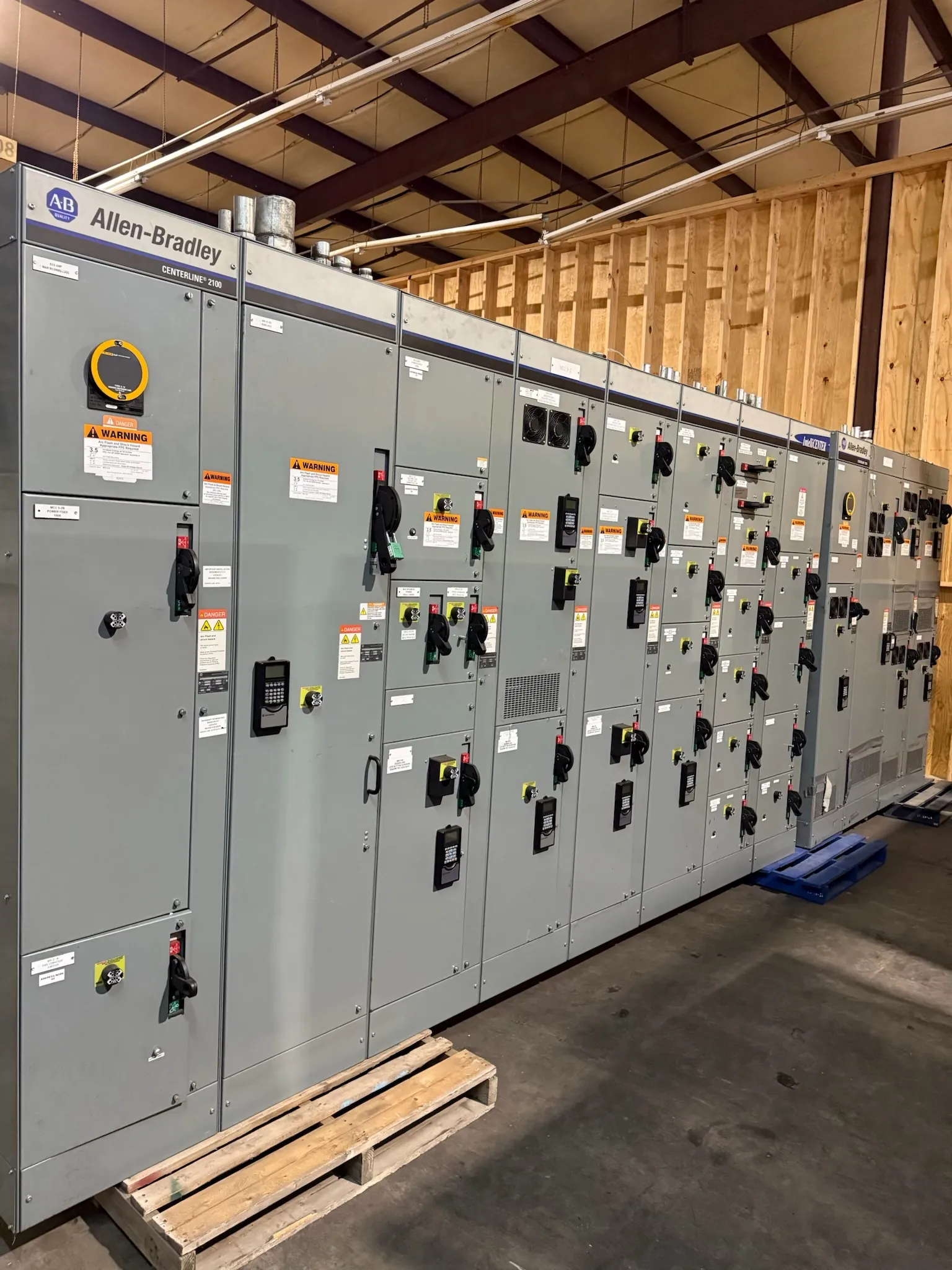
Hospital Switchgear for Las Vegas Electrical Distribution
Hospital electrical distribution in Las Vegas must be planned around the facility’s essential electrical system, utility service, emergency sources, and the loads that need power when normal service is interrupted. Switchgear and switchboards can provide the distribution and control interfaces for that system, but their configuration depends on the project’s electrical design and applicable requirements. A manufacturer can build new custom equipment to an approved design; it cannot determine the hospital’s life-safety strategy or substitute for the project engineer’s decisions.
For a Las Vegas project, confirm service characteristics and utility metering requirements before sizing the main section. The utility’s service arrangement, available fault current, metering interface, and the engineer’s specified system voltage and grounding approach affect equipment configuration. A rating printed on equipment is not the same as the system voltage. Proposed equipment ratings, construction, and any required listing must be checked against the final drawings, specifications, and site conditions.
Essential Electrical System Branches and Distribution Boundaries
Hospital essential electrical systems are organized into branches with different intended functions, as addressed by applicable provisions of NFPA 99 and related codes. The life safety, critical, and equipment branches are not interchangeable labels for a single backup panel. Their loads, transfer arrangements, circuit separation, and downstream distribution must follow the project design and the requirements applicable to the facility.
During equipment planning, the engineer should identify which branch circuits reach each switchboard or distribution section, where branch separation occurs, and which loads remain on normal power. That information helps define bus arrangements, feeder connections, compartment needs, and the space reserved for future circuits. A manufacturer should receive clear one-line diagrams and schedules rather than infer branch assignments from room names or general equipment descriptions.
Source Transfer, Generator Interfaces, and Coordination
Transfer equipment connects designated loads to alternate sources when normal power is unavailable. The selected arrangement may use separate transfer switches for different branches, with switching characteristics and locations established by the design team. Switchgear may interface with this equipment through feeder breakers, bus connections, control wiring, and status or alarm points. Those interfaces need to be documented so that the switchgear package and transfer equipment are compatible.
Generator capacity, starting characteristics, load sequencing, selective coordination, and protection settings influence how the system behaves during an outage and restoration. These are engineering decisions, not assumptions to resolve during fabrication. The electrical engineer should coordinate protective devices and transfer operation across normal and alternate sources, while the equipment manufacturer confirms that the specified devices, ratings, and physical arrangement can be provided as documented. Changes to loads or transfer logic after approval may affect the design and require renewed review.
Applying NFPA 99 and NFPA 110 to the Project
NFPA 99 addresses health care facility systems and includes provisions relevant to essential electrical systems. NFPA 110 addresses emergency and standby power systems, including equipment and performance considerations for those systems. Which provisions apply, and how they interact with adopted codes, authority requirements, facility classification, and project specifications, must be determined for the particular hospital by qualified design professionals and the authority having jurisdiction.
These standards do not establish one universal switchgear lineup for every hospital. Their requirements must be translated into project-specific drawings, equipment schedules, sequences, and acceptance criteria. The design team should identify applicable editions and requirements, including any project-specific interpretation. Equipment documentation can support that process, but no general product description establishes compliance or confirms a particular listing. UL 891 applies to applicable low-voltage switchboards; it should not be treated as a blanket designation for every switchgear product or system.
Quotation Inputs for a Las Vegas Hospital Project
A useful quotation package includes the latest one-line diagram, equipment schedules, specifications, service and metering details, available fault-current information, and the required ratings and construction. It should also show feeder quantities and sizes, incoming and outgoing cable or bus interfaces, branch assignments, device requirements, enclosure conditions, and control or communications points. For a renovation, plans should identify the intended tie-in boundaries and any dimensional or access constraints without relying on assumptions about existing equipment.
Las Vegas delivery planning should account for the site’s receiving hours, unloading method, route to the electrical room, door and corridor clearances, and any limits on staging or installation access. Those facility conditions can affect shipping sections, packaging, and coordination, even when the electrical design is unchanged. A U.S. manufacturer can build new custom assemblies using all-American components and ship nationwide; project-specific lead time and shipment details require confirmation when the design and scope are reviewed.
Submittals, Commissioning, and Responsibility Handoffs
Before release for manufacture, the project team should review equipment drawings, ratings, connection details, device selections, metering provisions, and interfaces with transfer equipment and generators. The engineer of record remains responsible for the electrical design and its coordination with the facility. The manufacturer is responsible for building the equipment to the approved scope and providing the agreed product documentation; the installing contractor is responsible for installation and field connections within its contract.
Commissioning and acceptance involve additional roles. The commissioning provider, owner, engineer, contractors, and other designated parties should establish the test scope, sequences, records, and acceptance criteria. The manufacturer may provide equipment information or agreed support, but commissioning responsibility and system-level results belong to the parties assigned those duties. Clear handoffs help ensure that submittal assumptions, field conditions, and final operating sequences remain aligned.