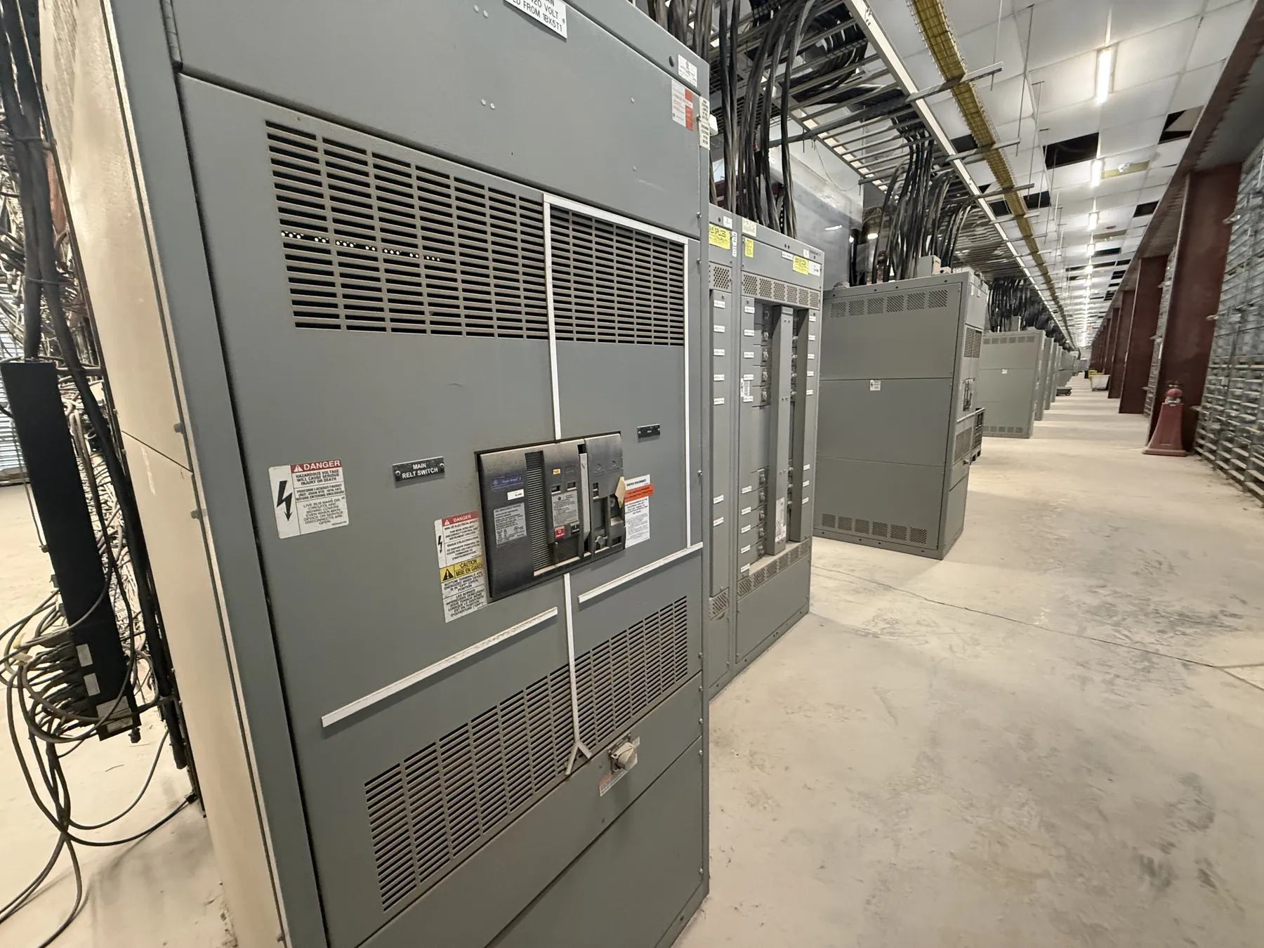
Medium-Voltage Switchgear for Hawthorne, NV Projects
Medium-voltage switchgear connects and protects circuits operating above the low-voltage range. For a Hawthorne project, selecting an assembly starts with the actual electrical system—not a product label alone. The design team needs to establish the system voltage and grounding arrangement, the available fault duty at the equipment location, and how power reaches and leaves the lineup. Those conditions affect insulation requirements, interrupting and withstand ratings, protective devices, and cable interfaces. A custom assembly can be manufactured for the project’s documented requirements; final suitability depends on engineering review of the source, connected equipment, and site conditions.
We manufacture new custom power-distribution equipment in the United States using all-American components. We serve customers in Nevada and ship nationwide; that does not mean equipment is manufactured at a Hawthorne facility. Project-specific design, component selection, and production planning begin with complete technical information so the proposed configuration can be evaluated before manufacture.
Establish Voltage Class, Fault Duty, and Insulation Level
“Medium voltage” describes a broad class, not one universal operating voltage or interchangeable rating. The project documents should identify nominal system voltage, highest system voltage where applicable, frequency, grounding method, and the equipment’s intended function. The selected voltage class and insulation level must suit the electrical system and the conditions at the installation point. They are related design parameters, but neither should be inferred from a general description of the facility.
Available fault duty is another essential input. It depends on the source and network configuration and can change when transformers, generators, utility feeds, or other sources operate in different combinations. Switchgear must be evaluated against the applicable short-circuit and momentary conditions, as well as the protective device requirements. A rating cannot be chosen responsibly from nominal voltage alone. The project engineer should confirm the study basis, assumptions, and required ratings for the proposed arrangement.
Match the Lineup to the Source and Distribution Arrangement
Describe whether the Hawthorne installation will receive power from one source or multiple sources, and identify any tie, transfer, generation, or alternate-feed arrangements that affect operation. The lineup may need incoming and feeder sections, metering provisions, protective devices, or provisions for future circuits. Those choices influence section layout, bus configuration, control interfaces, and the space and access needed for installation and service.
Source arrangements also shape protection and coordination. A normally open tie, parallel sources, or backup generation can produce different fault conditions and protection needs than a single radial feed. Interlocking and control logic should reflect the approved one-line diagram and operating philosophy. These details require qualified engineering review; they should not be settled by assuming that a standard lineup will fit every facility.
Select Relays and Protection Interfaces Deliberately
Protective relays are selected for the functions required by the system study and the equipment being protected. Depending on the design, those functions may include phase and ground overcurrent protection, voltage or frequency elements, transformer-related protection, or communication with supervisory controls. The required functions, instrument-transformer inputs, trip outputs, control power, alarms, and communications should be identified early. Relay capability alone does not establish a complete or coordinated protection scheme.
Coordination depends on source data, transformer characteristics, downstream devices, conductor information, and the intended operating modes. Relay settings and logic must be developed or reviewed by qualified professionals using project-specific studies. A quotation can define proposed relay hardware and interfaces when the requirements are supplied, but it should not be treated as a substitute for the protection study or approved settings.
Plan Cable Terminations and Physical Access
Cable termination details affect compartment design and installation planning. Provide the cable type and conductor information, termination method, entry direction, number of runs, and relevant routing constraints. The design team also needs to understand grounding provisions, phase arrangement, and any requirements for stress-control or termination components. These inputs help determine whether the proposed cable interface is compatible with the switchgear configuration; they do not replace the cable manufacturer’s requirements or the engineer’s review.
For a Hawthorne site, verify the equipment location, available working and installation space, access route, foundation or support conditions, environmental exposure, and constraints on lifting or delivery. Local facility conditions should be documented rather than presumed. Clear drawings and site information can reduce late changes to section dimensions, cable entry, or connection arrangements.
Prepare a Hawthorne Switchgear Quotation Package
To evaluate a custom medium-voltage switchgear request, provide the one-line diagram, system voltage and grounding data, fault-duty information, source scenarios, protection and relay requirements, cable details, and the intended lineup arrangement. Include relevant specifications, control schematics, interface requirements, site constraints, and the project schedule. If studies or site reviews are pending, identify them so the quotation can state which assumptions remain open.
Ratings, listing applicability, configuration, and project details require confirmation before manufacture. UL 891 applies to certain low-voltage switchboards; it is not a standard for medium-voltage switchgear. We can review the supplied requirements and develop a proposed new-equipment configuration for the project, with technical decisions subject to qualified engineering and site review. Early coordination among the owner, electrical engineer, installer, and equipment manufacturer helps clarify interfaces and supports practical planning for shipment to Hawthorne.