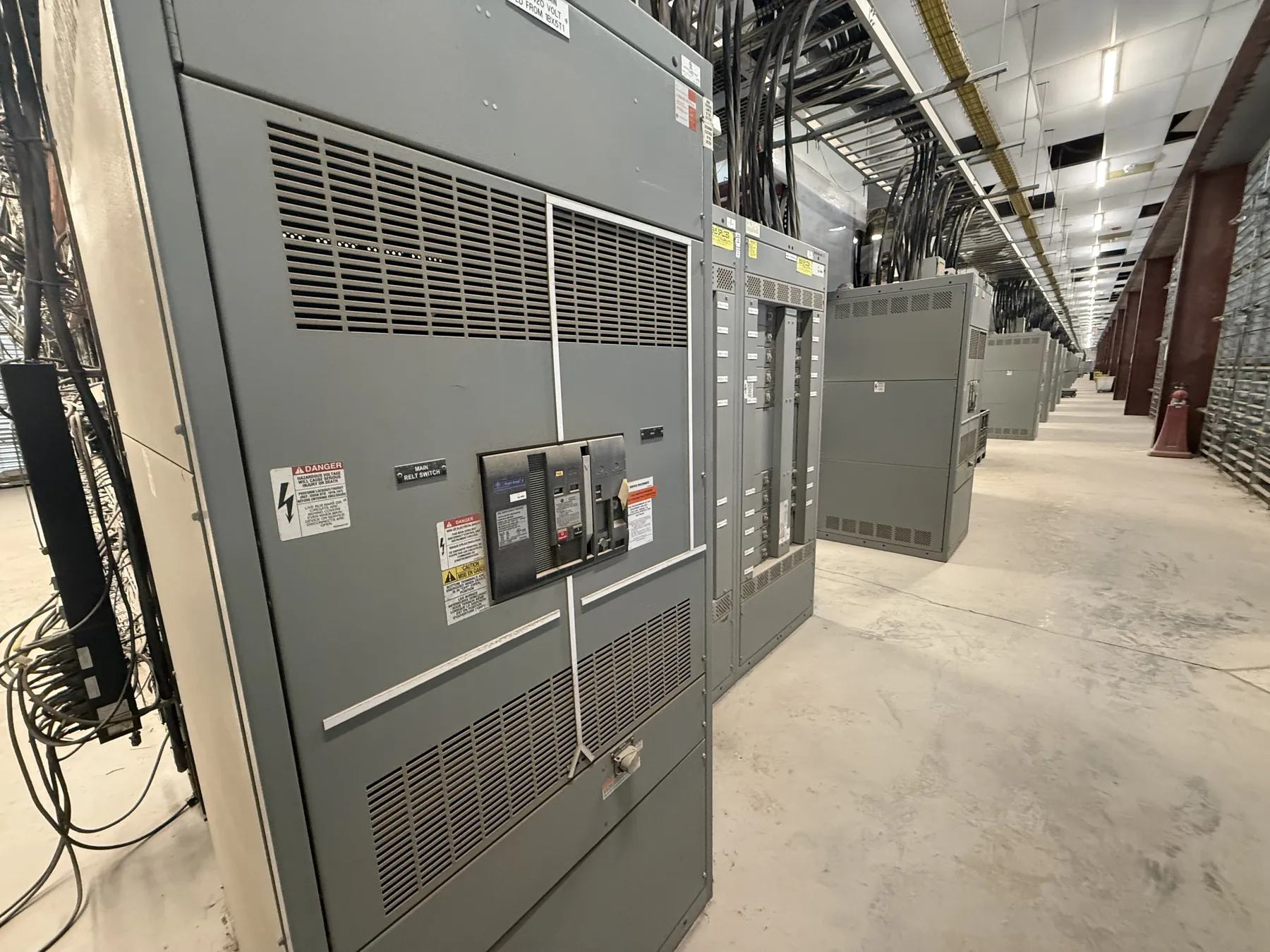
Pad-Mounted Switchgear for Gardnerville, Nevada Projects
Outdoor pad-mounted switchgear can provide a compact, enclosed point for switching and sectionalizing a distribution circuit. For a Gardnerville project, the equipment configuration should follow the electrical design and the actual site conditions—not a location name alone. Start by identifying the system arrangement, the circuits and loads involved, the required switching functions, and whether the equipment will connect to a utility or to customer-owned distribution. These details help determine the enclosure layout, switching and protection provisions, cable interfaces, and ratings that need engineering review.
New custom pad-mounted switchgear is manufactured for the project requirements. Assemblies use all-American components, are built in the USA, and can ship nationwide. Lead times depend on the approved design, component selection, and production requirements; a schedule should be confirmed for the specific order.
Enclosure Placement, Access, and Site Protection
Outdoor enclosures need a location that accommodates the equipment footprint and the practical needs of installation, inspection, and maintenance. Review vehicle routes, nearby structures, landscaping, drainage patterns, and the space needed to open doors or access operating compartments. Clearances and access provisions must be checked against the equipment design, applicable requirements, and the site plan by qualified project professionals.
Environmental protection is a design consideration, not a substitute for site review. The specification should describe exposure to precipitation, wind, dust, temperature variation, corrosive substances, and any other conditions identified for the installation. Enclosure construction and finish should be selected for the documented environment. Do not assume that a general outdoor designation resolves every exposure or establishes a specific degree of protection.
Foundation, Elevation, and Cable Entry
The foundation must support the equipment and align with its base and cable-entry arrangement. Before equipment details are finalized, coordinate the foundation drawing with civil and electrical plans, including conduit locations, entry direction, working space, and finished grade. Confirm that the installation elevation and site drainage are addressed. A foundation that is not coordinated with the enclosure can complicate cable installation or leave access and clearance issues to resolve in the field.
For Gardnerville sites, check the project elevation and the environmental specifications associated with the actual location. Elevation can be relevant to equipment application and ratings, while local site conditions affect enclosure, foundation, and cable-routing decisions. Do not infer suitability from a nearby installation or a city-level description. The responsible engineers should evaluate the project’s stated conditions and applicable equipment documentation.
Utility and Customer-Side Interfaces
Utility interfaces require early coordination when the switchgear connects to a utility distribution system. Confirm the proposed point of connection, ownership boundaries, metering needs, switching responsibilities, and any utility-specific interface requirements with the serving utility and project team. Utility practices vary, so a general product description cannot establish acceptance or approval for a particular connection.
Also identify the customer-side feeders, conductor types and sizes, termination approach, phase arrangement, and routing constraints. These inputs influence compartment arrangement and cable space. The one-line diagram and interface information should be reviewed together so the equipment configuration matches the intended circuit functions. Changes to the connection plan can affect layout and production, making early coordination valuable.
Ratings and Protection Must Match the Application
Equipment ratings describe defined capabilities under specified conditions; they are not interchangeable with the system’s nominal voltage. The project team must establish the system voltage and required equipment ratings separately, then confirm compatibility with the circuit conditions and protection scheme. Applicable switching, interrupting, and short-circuit requirements depend on the system design and the selected equipment. They should not be assumed from a voltage label or enclosure style.
Provide the available fault-current information, protection approach, operating sequence, and any required interlocking or sectionalizing functions for engineering review. Ratings, listings, and project-specific details require confirmation for the proposed assembly. UL 891 applies to applicable low-voltage switchboards; it should not be treated as a blanket standard for pad-mounted switchgear or as evidence that a particular configuration is listed.
Information to Prepare for a Gardnerville Quotation
A useful quotation request includes the latest one-line diagram, system voltage, required ratings, circuit and switching functions, utility-interface details, cable-entry preferences, and the intended indoor or outdoor placement. Include the site elevation and known environmental conditions, along with a site plan or foundation information if available. Identify schedule requirements and any project documents that govern enclosure appearance or interfaces. Missing information can leave important design choices unresolved, so preliminary selections should be clearly identified as such.
Before release, coordinate the equipment submittal with the electrical, civil, and utility stakeholders. Confirm that the drawings reflect the final conduit and foundation plan, cable approach, access requirements, and protection scheme. This review helps ensure that the manufactured assembly is designed for the actual Gardnerville installation rather than relying on assumptions about a typical outdoor site.