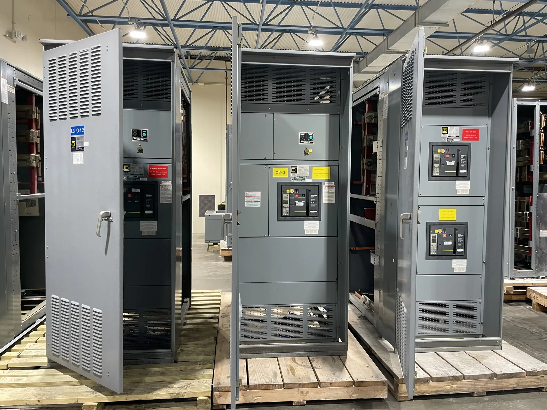
Motor Control Centers for Fernley, Nevada Facilities
Motor control centers (MCCs) group motor-control and distribution components into coordinated sections, helping a facility organize equipment for pumps, fans, conveyors, compressors and other motor-driven loads. For a Fernley project, the right arrangement depends on the process, electrical service, building conditions and how operators and maintenance staff need to access the equipment. A new MCC can be configured around those project requirements rather than selected by motor count alone.
Our U.S.-built equipment uses all-American components and is manufactured for customer projects, with short lead times supported and shipment available nationwide. Final configuration, ratings and schedule depend on the approved application and should be confirmed during project review. A Nevada destination does not by itself determine the appropriate design; the site’s electrical and operational conditions do.
Motor Starters, Drives and Control Interfaces — Motor Control Centers in Fernley, NV
Starter selection begins with each motor’s nameplate and duty. Across-the-line starters may suit some loads, while other applications call for reduced-voltage starting or variable-frequency drives (VFDs). The decision affects starting behavior, control requirements, heat, available space and coordination with upstream electrical equipment. A motor schedule that identifies horsepower, voltage, full-load current, starting method and duty cycle gives engineers a useful basis for evaluating options.
VFD integration requires attention beyond fitting a drive into a section. Engineers need to review drive ratings and environmental requirements, heat dissipation, control wiring, communications interfaces and the relationship between the drive and the motor. The project should also identify who supplies external controls, sensors, network connections and programming. If drives are located separately from the MCC, cable routing and control interfaces still need to be coordinated across the equipment boundary.
Short-Circuit Ratings and Feeder Protection — Motor Control Centers in Fernley, NV
An MCC’s short-circuit rating is not the same as the facility’s system voltage, nor can it be selected from a general description of the site. The available fault current, upstream protective device and equipment configuration all matter. The responsible electrical engineer should establish the required rating using project-specific system information and confirm that the selected equipment and protective devices are suitable together.
Feeder protection must also match the loads and the intended distribution arrangement. Breakers or other protective devices are selected and coordinated as part of the electrical design, not simply according to the number of outgoing circuits. Review the source, feeder conductors, motor branch circuits, overload protection and relevant coordination requirements together. Changes to the source or upstream protection can affect the equipment rating and design basis, so updated project data should be shared before an order is finalized.
UL 845 and Applicable Equipment Requirements — Motor Control Centers in Fernley, NV
Confirm whether UL 845 is required for the MCC in the project specification, procurement documents or applicable authority review. Its applicability and the requested listing or certification status must be checked for the proposed equipment and scope. Do not assume that a standard or listing for one product category applies to every assembly or installation. Requirements may differ according to equipment type, intended use and project documents.
Provide the specification section, one-line diagram and any owner or engineer requirements when requesting a proposal. The project team should verify the applicable standards, ratings and listing details before release. Electrical design decisions and code interpretations require qualified engineering review and consideration of the actual site conditions.
Fernley Site Conditions, Source Reliability and Access
For a Fernley facility, confirm where the MCC will be installed: indoors or outdoors, in conditioned or unconditioned space, and near sources of dust, moisture, corrosive exposure or vibration. These conditions can affect enclosure selection, component suitability, ventilation and maintenance planning. Room dimensions, doorways, access routes, floor conditions and the planned arrangement of adjacent equipment also influence section layout and installation logistics. Site measurements and equipment-handling constraints help prevent avoidable conflicts during delivery and placement.
Discuss power-source reliability needs with the project engineer. Identify whether the design involves a single source, alternate source, standby generation or another arrangement, and clarify what functions must remain available during a source interruption. Those needs may affect feeder organization, control interfaces and the broader distribution design. They cannot be resolved by the MCC configuration alone; source capacity, protection, transfer equipment and operational requirements must be reviewed as a coordinated system.
Spare Feeders, Maintenance Access and Quotation Inputs
Spare feeder requirements are easiest to address before the lineup is finalized. Specify the number and type of future circuits, expected load information if known, and whether spare spaces need to be fully equipped or reserved for later configuration. Spare capacity should not be treated as a substitute for confirming bus, enclosure and short-circuit requirements. Maintenance access also deserves early attention: consider working clearances, access to removable components, cable entry, labeling and the relationship of the MCC to nearby walls and process equipment.
For a useful quotation, provide the motor schedule, one-line diagram, control requirements, available fault-current information, source details, site environment, desired lineup arrangement and applicable specification. Include requested spare feeders, VFD quantities and interfaces, installation constraints, and required submittal or listing documentation. These inputs support a project-specific review of equipment scope, ratings and schedule; final selections remain subject to engineering confirmation and site review.