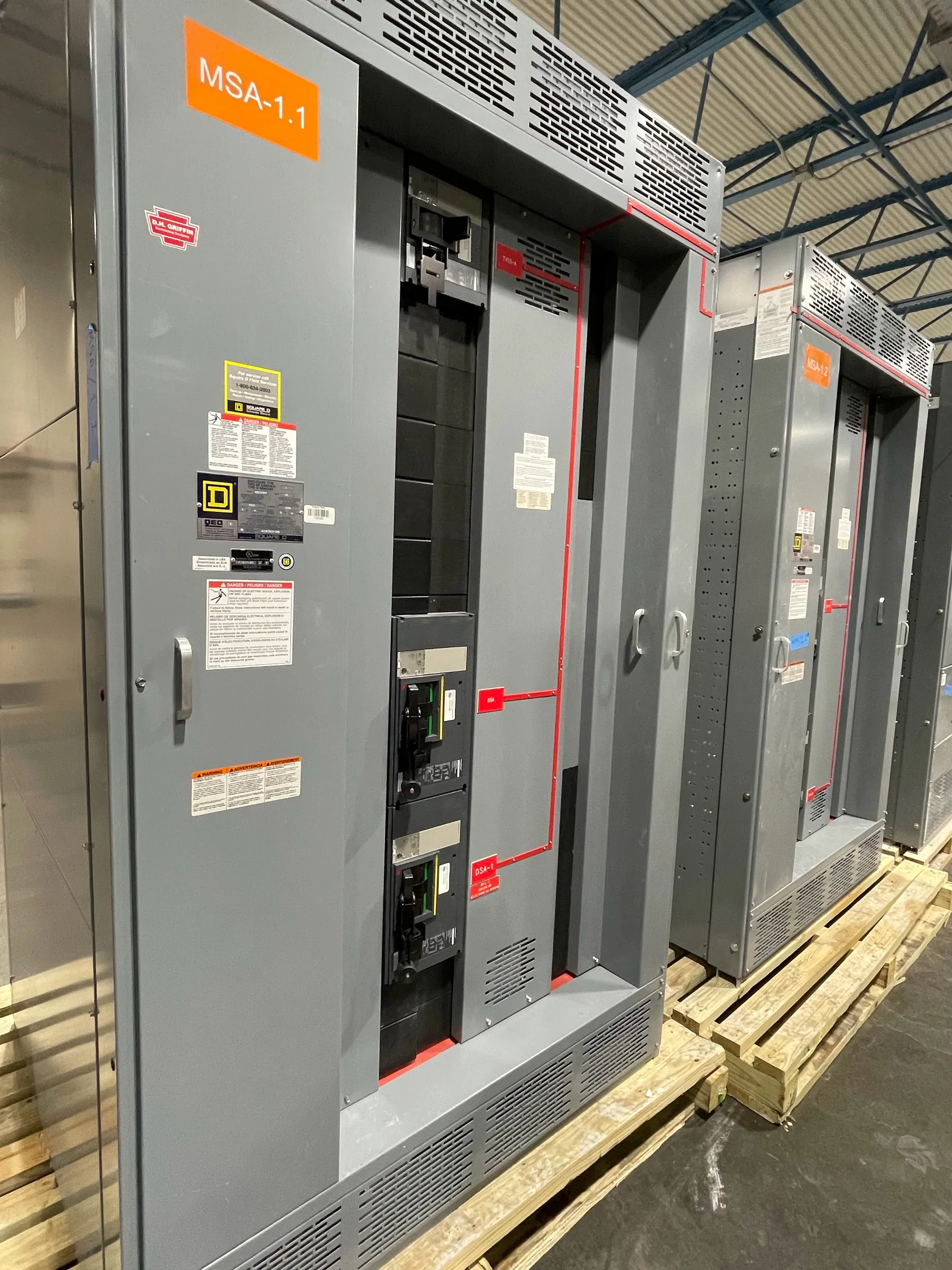
University Electrical Distribution Planning for Elko Campuses
Campus electrical distribution has to serve more than classroom buildings. A university project in Elko may involve teaching spaces, research laboratories, residence halls, dining facilities, libraries, central services and outdoor infrastructure, each with different load patterns and consequences when power is interrupted. New custom switchgear and power-distribution equipment can be designed around the project requirements, but the first step is a clear picture of the existing system and the work the campus intends to perform.
For an Elko project, document the actual site conditions rather than relying on a generic campus specification. Include the specified ambient conditions, indoor or outdoor location, enclosure requirements, equipment-room dimensions, access routes and maintenance clearances. Elevation, seasonal conditions and exposure to dust or moisture may affect design inputs; the project engineer should establish which conditions apply and how they influence the equipment specification.
Campus Feeders, Building Interfaces and Continuity Needs
Feeder planning starts with the one-line diagram and the relationship between the proposed assembly, upstream source and downstream distribution. Identify feeder destinations, conductor and termination requirements, protection and coordination expectations, available fault-current information, and any tie or alternate-source arrangements. The design team must verify system voltage, equipment ratings and compatibility with existing gear; a rating is not a substitute for confirming the electrical characteristics of the connected system.
Universities often need to distinguish loads that can tolerate a planned outage from those that require a separately engineered continuity strategy. Research processes, building controls, data systems, life-safety systems and essential services may have different requirements. Document which loads are served by normal, emergency or other project-defined sources, and have qualified engineers coordinate the equipment interfaces and applicable requirements. Do not assume that a particular switchboard arrangement provides backup power or uninterrupted service by itself.
Laboratory Loads, Metering and Future Flexibility
Laboratories can combine general receptacle loads with specialized instruments, ventilation, environmental controls and equipment that operates on distinct schedules. Provide load schedules and the relevant electrical characteristics for laboratory equipment, including known starting behavior or power-quality sensitivities where the design team has established them. Identify planned laboratory expansions separately from existing demand so that future provisions are intentional rather than based on unverified assumptions.
Metering scope also needs definition. Decide which buildings, feeders or operational groups require measurement, what information the campus energy or building-management systems need, and who will provide compatible communications interfaces. Specify whether the project calls for revenue-grade, operational or other metering only when the responsible engineer and owner have determined the requirement. Metering can support energy review and troubleshooting, but it does not replace protection, system studies or verification of actual loads.
Staged Renovation Around an Active Campus
Phased work can reduce disruption, but only when the construction sequence matches the existing distribution layout and campus operating calendar. Provide existing one-lines, equipment schedules, available field survey information and a description of planned outage windows. Identify which buildings or functions must remain in service during each phase, and explain how temporary arrangements, cutovers and final connections are expected to be coordinated by the project team.
Space and access can be as consequential as electrical ratings. Confirm the route from receiving to the equipment room, doorway and corridor constraints, floor loading information where relevant, working and maintenance clearances, and any restrictions on staging or lifting. For Elko deliveries, coordinate the receiving point, site access, unloading responsibilities and construction sequence with the campus facilities and contractor teams. These details help the manufacturer evaluate the specified assembly and packaging requirements without assuming a particular site layout or delivery arrangement.
Specification and Quotation Inputs for Custom Equipment
A useful quotation package should describe the requested equipment and the project interfaces, not just name a product category. Include the latest one-line diagram, project specifications, load and feeder schedules, system information, enclosure and environmental requirements, metering scope, and known installation constraints. State requested options, documentation needs and the project schedule assumptions. Flag missing or provisional information so it can be resolved instead of silently treated as confirmed.
Ratings, product configuration, applicable listings and code requirements must be reviewed against the specific design and jurisdiction. UL 891 applies to applicable low-voltage switchboards; it should not be treated as a blanket designation for all switchgear or other distribution products. The responsible engineers must confirm the intended equipment type, ratings and applicable requirements. A U.S. manufacturer can build new custom equipment with all-American components and ship nationwide, including to Nevada; final scope, schedule and shipment details depend on the approved project requirements.
Facilities Coordination, Access and Long-Term Serviceability
Bring campus facilities staff, the electrical engineer, contractor, controls team and equipment manufacturer into the discussion early enough to resolve interface questions. Confirm who owns field verification, system studies, protection settings, communications integration, installation and commissioning responsibilities. Provide maintenance-access expectations and any campus standards for labeling, documentation or spare provisions. Clear responsibility boundaries help prevent gaps between the equipment specification and the broader electrical design.
Before release, review the final drawings and submittals against the project’s current one-line, room conditions and phasing plan. Confirm that dimensions, incoming and outgoing connections, metering interfaces, enclosure details and stated ratings match the approved design. This disciplined review gives an Elko university project a practical basis for coordinating new distribution equipment with campus operations while leaving engineering decisions with the qualified professionals responsible for the site.