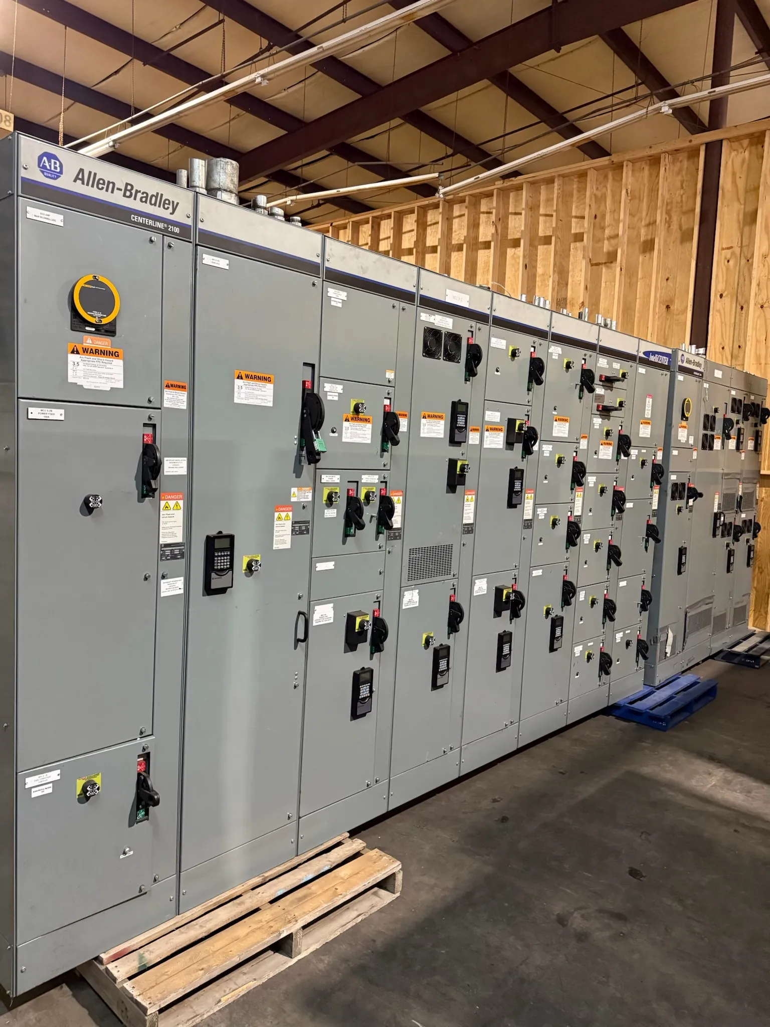
Commercial Switchgear Planning for Elko Buildings
Commercial electrical distribution in Elko starts with how a building is used, not simply with a cabinet size. Retail spaces, offices, lodging, workshops and mixed-use facilities can place different demands on service equipment and tenant feeders. A custom assembly should reflect the planned service arrangement, connected loads, metering strategy and operating responsibilities for the actual project. Early coordination among the owner, electrical engineer, contractor and serving utility helps establish an equipment scope that fits the building rather than relying on assumptions about local service or future tenants.
For projects in Elko, equipment is manufactured in the United States using all-American components and can ship nationwide. Shipping to a Nevada site is not the same as having a local manufacturing facility or office; project-specific freight, receiving and installation arrangements should be coordinated by the project team.
Tenant Feeders, Metering and Service Interfaces
Where a building has multiple suites, the distribution plan should make clear which loads are served from house panels and which are assigned to tenant panels. Feeder quantities, breaker provisions and space for metering depend on the lease arrangement and the engineer’s design. Separate tenant metering may be required, preferred or unnecessary depending on the project and utility rules. Confirm who supplies, owns and maintains each metering component, and whether the utility requires particular meter locations, compartments or service arrangements.
Service equipment also has to match the utility’s approved point of connection and the project’s one-line diagram. Confirm service voltage, phase, conductor approach, service disconnect requirements and any utility-specific construction details before finalizing a switchboard layout. These interfaces can affect enclosure arrangement, bus configuration and the space needed for incoming conductors. Utility acceptance and service availability are determined through the applicable utility and project processes, not assumed from the equipment quotation.
Capacity for Planned Loads and Future Changes
Future capacity is not just a larger main rating. It may involve physical section space, provisions for additional feeder devices, bus capacity, metering positions and a service design that can accommodate expected building changes. Identify known additions—such as new tenant areas, kitchen equipment, electric heating, vehicle charging or larger mechanical loads—and have the project engineer evaluate their impact. Unused breaker spaces do not by themselves establish that the bus or service can carry a future load.
Ratings must be reviewed in context. Equipment ampere ratings are not the same thing as system voltage, and the required voltage and short-circuit ratings depend on the electrical design and available fault current at the installation point. A qualified engineer should verify these values against the site and system. If a low-voltage switchboard is specified, UL 891 may be relevant to that product category; applicability, listing status and the exact equipment configuration must be confirmed for the order.
Elko Site Conditions, Enclosures and Access — Commercial Switchgear in Elko, NV
Document the conditions where the equipment will actually be installed. These may include indoor or outdoor location, ambient temperature range, moisture exposure, dust, corrosive agents, elevation where relevant to the design, and the presence of heating or ventilation. Enclosure construction should follow those conditions and the project specification rather than a broad assumption about the city. An outdoor location, for example, can require different enclosure provisions from a controlled electrical room, but the required construction depends on exposure and applicable design criteria.
Show the equipment footprint and working space on coordinated drawings. Door swing, aisle width, wall location, cable entry and access to serviceable components can affect whether an otherwise suitable lineup fits the room. Required working clearances are governed by applicable code, equipment configuration and site conditions; have the project’s qualified electrical professionals verify them. Maintenance access should be considered alongside installation access, including how technicians will reach the intended service points without blocking adjacent equipment or building routes.
Information That Improves a Custom Equipment Quotation
A useful request package gives the manufacturer enough information to identify the intended assembly and flag unresolved interfaces. Include the latest one-line diagram, equipment schedule, service and system ratings, feeder list, metering requirements, available fault-current information, enclosure requirements, conductor entry details and room layout when available. Note the project stage and identify any items still under utility or engineering review. Drawings and specifications should also indicate whether the scope includes specific sections, devices, controls or accessories.
Changes to tenant count, load assumptions or utility requirements after quotation can affect the arrangement and should be communicated promptly. Final ratings, listings, dimensions and configuration require confirmation against approved project documents. The quotation process can clarify equipment scope, but it does not replace electrical engineering, code review or site verification.
Coordinating Delivery and Installation in Nevada
For an Elko project, confirm the delivery address, receiving hours, unloading capability, site access and planned construction sequence with the contractor and freight coordinator. Remote or constrained sites may require additional coordination for truck access, staging and protection from weather, but those conditions vary by facility. Share installation timing and any limits on temporary storage early, without treating an estimated shipment schedule as a guaranteed project date.
Custom commercial switchgear works best when distribution design, utility interfaces, building conditions and maintenance needs are resolved together. A complete, coordinated specification gives the manufacturer a clearer basis for preparing equipment to the project requirements and helps the installing team plan around the actual site.