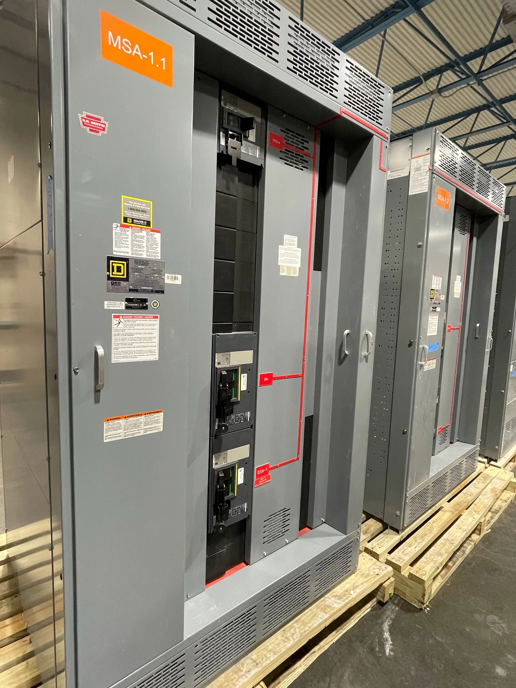
Service Entrance Switchboards for Dayton Projects
A service entrance switchboard is where a building’s incoming electrical service, utility metering arrangement and main disconnect come together. For a Dayton project, the service section should be developed around the serving utility’s requirements, the building’s electrical design and the authority having jurisdiction—not selected by nameplate voltage alone. Early coordination helps establish how conductors enter the equipment, where metering belongs and what space is needed for installation and future access.
We manufacture new custom switchboards in the United States using all-American components and serve Nevada projects with nationwide shipping. A preliminary equipment discussion can identify the information needed for a project-specific design and quotation. Final ratings, construction details, listing applicability and approval requirements must be confirmed by qualified electrical professionals and the responsible utility and authorities.
Resolve Metering and the Service Boundary First
Utility metering can affect the switchboard’s layout, compartment arrangement, access provisions and the relationship between utility-owned and customer-owned conductors. The project team should confirm whether metering is installed in or beside the switchboard, which components the utility specifies, and how the utility expects its equipment and wiring to interface with the service section. Requirements can vary by utility and project, so a generic metering arrangement should not be assumed to satisfy local review.
Identify the service point and ownership boundary on the one-line diagram, then provide available utility service details and any written metering guidance with the equipment inquiry. These details help distinguish the incoming service compartment from downstream distribution sections and clarify what must remain accessible to utility personnel. A change in the metering approach can alter equipment dimensions and connection locations, making early confirmation valuable.
Coordinate the Main Disconnect, Grounding and Fault Duty
The main disconnect must be selected for the project’s electrical design, service configuration and required operating arrangement. Its rating is not interchangeable with system voltage: voltage describes the electrical system, while equipment ratings address specific performance limits and must be evaluated against the design. The engineer should establish the applicable system characteristics, main-device requirements and downstream coordination approach before the switchboard is finalized.
Service grounding and bonding details also require deliberate coordination. The design team should define the service grounding method, neutral and grounding connections, and the point at which bonding occurs in accordance with the applicable design and code requirements. Available fault current at the equipment is a separate critical input. It must be determined for the actual service location and reviewed against the proposed equipment ratings and protection scheme; it should not be inferred from nominal voltage or a typical building type.
Plan Dayton Cable Entry and the Equipment Room
Dayton site conditions can shape the enclosure and installation sequence even when the electrical design is already established. Confirm whether service conductors enter from above, below or another defined route, and provide the intended raceway or cable locations. Entry direction affects section arrangement, conductor bending and the space needed to bring cables to their terminations. Late changes can create conflicts with the building structure, underground service route or adjacent equipment.
Review floor loading and the planned route from delivery point to final location with the structural and installation teams. Equipment dimensions, section configuration and handling constraints should be considered alongside doorways, corridors, overhead obstructions and the switchboard room’s finished floor. Preserve required working space and access based on the applicable design and code review. The room layout should also account for wall conditions, nearby services and any future sections or feeder pathways the project expects to accommodate.
Build the Quote Around Reviewable Project Inputs
A useful quotation package includes the latest one-line diagram, service and system information, utility metering requirements, available fault-current data and the intended main-device arrangement. Include conductor entry direction, connection details, feeder quantities and relevant schedules where available. Room dimensions, access restrictions, floor information and the desired installation sequence help identify physical constraints that a single-line drawing may not show.
Also identify the project’s approval pathway and required submittal documents. Applicable standards and listings depend on the equipment type and configuration; UL 891 applies to applicable low-voltage switchboards, not every switchgear assembly or every voltage class. Any requested listing, rating or utility acceptance must be verified for the specific proposed equipment and project. Provide outstanding questions rather than treating unconfirmed details as settled specifications.
Coordinate Reviews Before Release and Installation
Before the design is released for manufacture, the electrical engineer, utility, equipment manufacturer, installer and authority having jurisdiction should resolve interfaces that affect the service entrance. Review the metering compartment, grounding and bonding plan, fault-current basis, main disconnect, cable landing space and equipment-room clearances together. Confirming these items on project drawings can reduce redesign and help align manufacturing, site preparation and installation planning.
Our team manufactures new custom power-distribution equipment for customers and ships nationwide, including to Nevada. Lead time depends on the project’s approved configuration, material and design requirements, so timing should be established during quotation and submittal coordination rather than assumed. Dayton project teams can begin with confirmed utility information and site constraints, then refine the switchboard configuration through qualified engineering review.