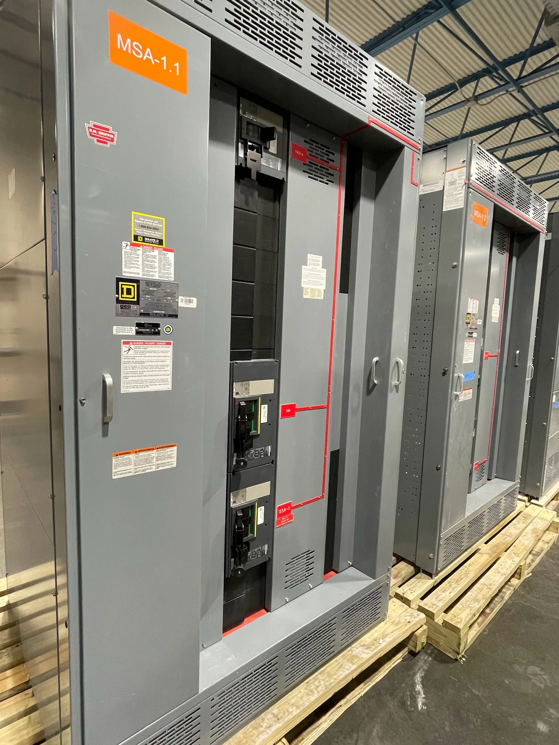
Wastewater Switchgear Planning for Dayton, NV Facilities
Wastewater electrical distribution must be planned around the facility’s process loads, operating priorities and physical environment—not just a list of motor horsepower values. For a Dayton project, the right switchgear or switchboard arrangement depends on the incoming source, the equipment being served, the desired degree of isolation and how the assembly will be moved into its final position. A custom design can bring distribution, protective devices and control interfaces together in an arrangement suited to the project, subject to review by the responsible electrical engineer.
Early discussions should identify whether the equipment serves lift stations, treatment processes, headworks, aeration, solids handling or a combination of loads. These applications can have different starting patterns and operating sequences. The equipment lineup should reflect which loads may operate together, which require separate feeders, and which functions need to remain available when another part of the process is out of service.
Pump and Motor Loads Shape Feeder Choices
Pumps and other motor-driven equipment influence feeder sizing, protective-device selection and the way the distribution assembly is divided. Relevant details include motor nameplate information, starting method, expected operating sequence, control voltage requirements and any variable-frequency drives or soft starters specified by the project. A motor’s full-load current alone does not establish the complete feeder or switchgear design; starting conditions, protection coordination, conductor selection and applicable codes also matter.
Where several pumps can run at once, the engineer should provide the intended duty and standby arrangement and identify any overlap during process transitions. Dedicated feeders may help make isolation and fault coordination more specific, while a shared arrangement may affect how loads are grouped and maintained. The final choice depends on the one-line diagram, control scheme, upstream protection and operational requirements—not simply on the number of motors.
Standby Power and Essential Process Loads
If standby power is part of the facility plan, define its source and boundaries early. The design team needs to know which loads are expected to transfer, whether transfer equipment is separate or integrated into the distribution plan, and how the normal and standby sources will be isolated and coordinated. Emergency and legally required systems, where applicable, have distinct code and design considerations that must be established by qualified project professionals.
Not every wastewater load necessarily belongs on standby power. The owner and engineer should identify the process functions that must continue, the loads that can be shed, and any starting sequence needed to avoid overloading the standby source. Those decisions affect feeder grouping, controls, protective-device coordination and available space in the equipment lineup. Generator details, transfer equipment interfaces and the approved one-line diagram are important quotation and design inputs.
Moisture, Corrosion and Enclosure Selection — Wastewater Switchgear in Dayton, NV
Wastewater sites may include damp rooms, washdown areas, chemical exposure or outdoor installations, but conditions vary by location within a facility. The enclosure should be selected for the actual exposure and installation environment. An appropriate enclosure rating is not a general promise of protection from every contaminant or condition; it must match the project’s stated requirements and the equipment’s intended location. The engineer should also consider ventilation, condensation, access and any cleaning practices near the assembly.
Where corrosion is a concern, specify the exposure rather than relying on a broad description such as “harsh environment.” Identify nearby chemicals, expected humidity, washdown practices, outdoor exposure and any special material or finish requirements. These conditions can affect enclosure construction, hardware choices and maintenance access. The final configuration and any applicable listing or rating require confirmation for the particular equipment and installation.
Dayton Layout, Access and Installation Coordination
Before a lineup is finalized, confirm the route from delivery point to equipment room, including door openings, turns, overhead constraints and any limits on handling or staging. Cable entry location—top, bottom or another project-defined arrangement—should be coordinated with conduits, cable tray, trenching and the positions of other electrical equipment. Changes to entry direction late in design can affect internal layout and field connections.
Floor loading and anchorage should be reviewed against the equipment configuration and the facility’s structural conditions. Working space, door swing, access to operating handles and clearance for future maintenance must be coordinated with applicable codes and the site layout. The owner or contractor should also establish the desired installation sequence, including when the assembly can enter the building, how it will be positioned, and when field cables and control interfaces will be ready. These are project-specific checks, not assumptions that can be resolved from the city name alone.
Information for a Custom Switchgear Quotation — Wastewater Switchgear in Dayton, NV
Useful quotation inputs include the one-line diagram, system voltage, available fault-current information, required equipment ratings, feeder schedule, motor and drive data, control and monitoring interfaces, enclosure conditions, cable-entry preference, and physical dimensions or room drawings. Identify any specified standards, listing requirements and project documentation expectations. UL 891 applies to applicable low-voltage switchboards; it should not be treated as a blanket designation for every switchgear assembly or voltage class. Ratings, listings and scope must be confirmed for the proposed product and project.
We manufacture new custom power-distribution equipment in the United States using all-American components, with short lead times supported by project review and nationwide shipping, including to Nevada. Actual schedule depends on the confirmed design, required components and project documentation. Qualified engineers and the site team must resolve system design, code compliance, protection coordination and installation conditions before the equipment configuration is finalized.