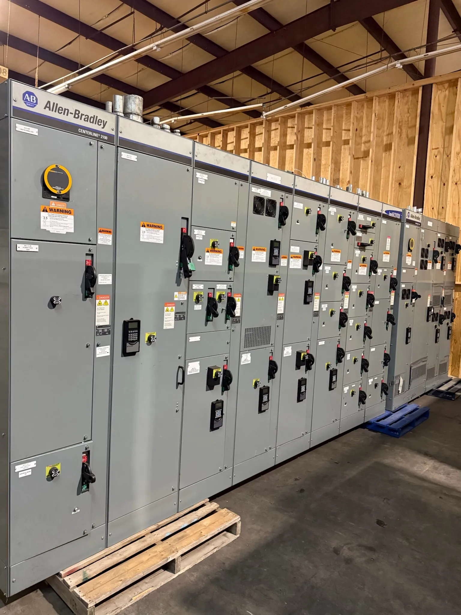
Pad-Mounted Switchgear for Dayton, Nevada Projects
Pad-mounted switchgear provides an outdoor point for switching and sectionalizing power circuits, with the equipment enclosed in a grounded, weather-resistant cabinet. For a Dayton project, the design must fit the electrical plan as well as the site: available footprint, access route, underground duct layout, soil and drainage conditions, and nearby buildings or other equipment all matter. A workable specification starts with the intended circuit arrangement and utility interface, then coordinates the enclosure, foundation, cable entry and ratings with the project drawings.
We manufacture new custom power-distribution equipment in the United States using all-American components. Assemblies can be configured around project requirements, but final design details depend on engineering review and confirmation of the application. We ship nationwide, including to Nevada; shipping does not establish that a particular site, utility or installation is approved for a given design.
Outdoor Enclosure, Access and Environmental Protection
An outdoor enclosure must protect its internal components from the conditions expected at the installation location while allowing the specified equipment to be accessed and maintained. Enclosure material, finish, door arrangement, compartment separation and locking provisions should be selected with the exposure and operating concept in mind. The project team should assess sun exposure, windblown dust, precipitation, irrigation overspray, standing water and the possibility of vehicle or landscaping impacts. Dayton site conditions vary, so assumptions about exposure should be checked against the actual site rather than treated as universal.
Cabinet layout also affects practical access. Door swing, removable panels, lifting provisions and clear working space should be coordinated with fences, walls, sidewalks, parked vehicles and adjacent electrical equipment. The equipment footprint alone does not define the space needed around it. The responsible electrical designer and site team should verify applicable working-space requirements and access constraints using project conditions and governing codes.
Foundation, Floor Loading and Installation Sequence
The pad or other supporting foundation must suit the equipment configuration and the site’s structural and civil design. Project coordination should address the equipment footprint, mounting details, conduit stub-up locations, anchorage, drainage and the load transferred to the foundation. Floor or foundation loading cannot be confirmed from a product name alone; it depends on the final assembly and support conditions. The structural engineer should review equipment information and site documents before the foundation is finalized.
Installation sequence is another early design input. Confirm how the equipment will reach its final position, whether lifting and setting access is available, and when underground conduits and the foundation must be ready. Cable routing, concrete work, equipment placement and adjacent construction can compete for the same space. Resolving these interfaces before fabrication can reduce field changes, though the project schedule and sequence remain specific to the contractor and site.
Cable Entry and Underground Duct Coordination
Cable entry should be developed from the one-line diagram, cable schedule and civil drawings, not left to a general note. The design team should identify which compartments receive incoming and outgoing cables, the number and arrangement of conductors, conduit sizes and entry locations, and any required separation between circuits. Bend radius, pulling access and working room inside the enclosure can constrain entry positions. Duct banks should align with the approved equipment layout and foundation openings.
Before release, compare the proposed cable path with actual site elevations and obstacles. Check for conflicts with other utilities, drainage features, roadways and future construction. Cable type, termination arrangement and conductor details must be confirmed by qualified project personnel; they influence compartment geometry and may affect the selected equipment configuration.
Utility Interface and Project-Specific Ratings
Utility interface requirements need direct coordination with the serving utility and the project’s electrical engineer. Relevant inputs may include the required switching arrangement, incoming source configuration, connection point, metering or other interface provisions, operating responsibilities and any utility-specific drawings or review process. Requirements vary by service and location. A custom assembly should not be assumed acceptable to a utility until that utility has reviewed and accepted the applicable project information.
Specify electrical ratings for the actual system and duty. Equipment voltage rating, continuous current rating and short-circuit capability are separate considerations; none can be inferred solely from the nominal system voltage. The design team must establish the available fault conditions, system grounding, switching needs and applicable specifications. A rating, listing or construction standard applies only where it is appropriate to the specific equipment and is confirmed for the quoted configuration. UL 891 concerns applicable low-voltage switchboards; it should not be treated as a blanket standard for pad-mounted switchgear.
Information for a Dayton Equipment Quotation
A useful quotation package helps resolve configuration and interfaces before production planning. Provide the project one-line diagram, site or civil layout, proposed foundation details, cable and conduit schedule, required equipment ratings, utility criteria and anticipated installation sequence. Include the expected environmental exposure, access limitations and any constraints on enclosure dimensions or door orientation. Identify which details are fixed and which remain under engineering review.
With these inputs, the equipment configuration can be evaluated against the project’s electrical and physical requirements. Lead time depends on the finalized scope and coordination, so it should be confirmed for the specific order rather than assumed. For Dayton installations, early communication among the owner, electrical engineer, utility, civil team and installer helps align the enclosure, foundation, cable paths and site logistics before the equipment is released for manufacture.