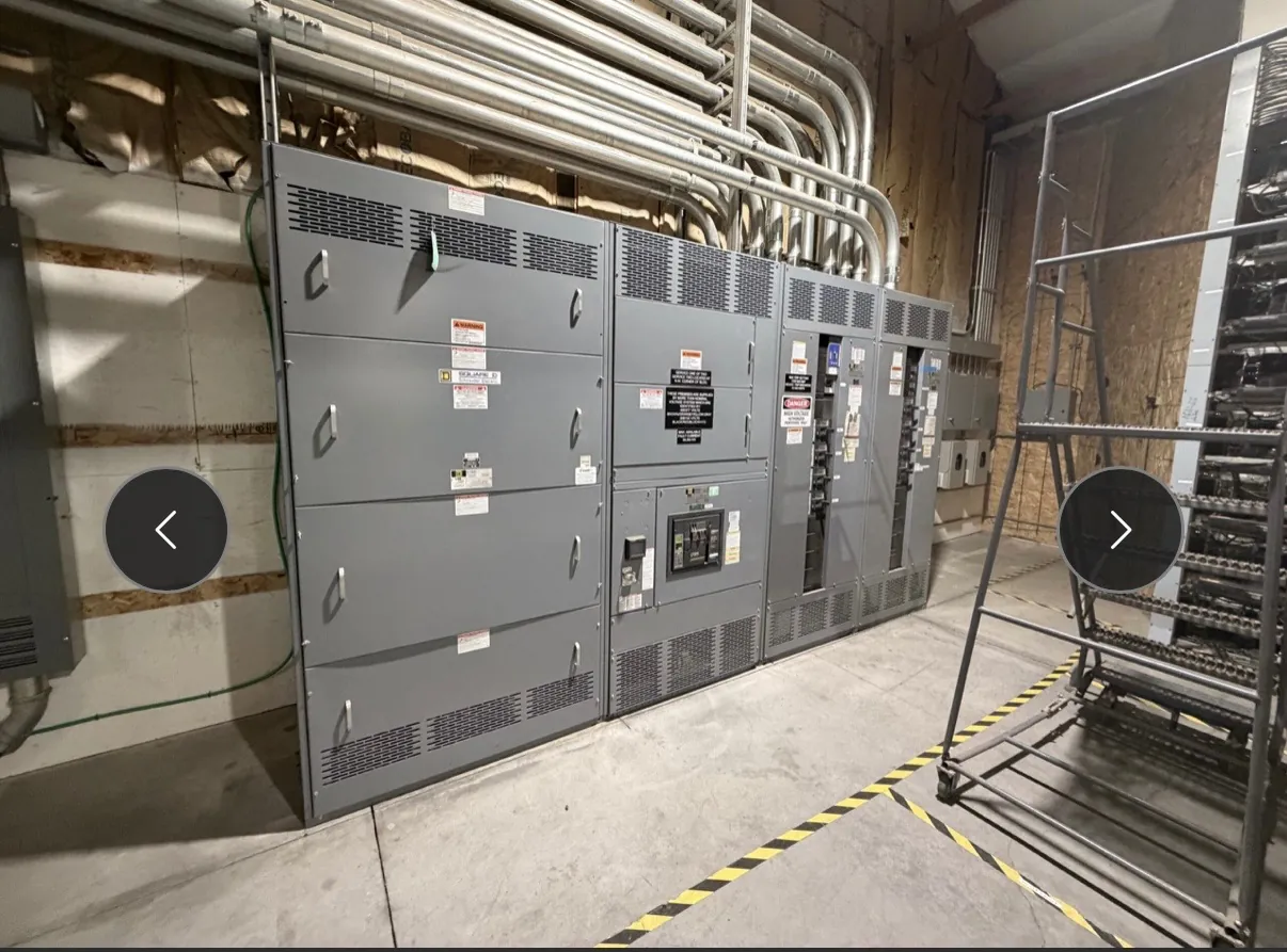
Data Center Switchgear Planning for Dayton Facilities
Data center electrical distribution has to support the facility’s intended redundancy, load growth and maintenance strategy—not just deliver power from an incoming source to panels. For a Dayton project, begin with the one-line diagram and define how utility service, generators, UPS equipment, switchboards and downstream distribution connect. Identify normal and alternate paths, the loads assigned to each path, and the conditions under which a transfer or bypass is expected. These decisions shape the equipment arrangement and determine which interfaces must be coordinated before fabrication.
Our U.S.-manufactured custom switchgear and power-distribution assemblies use all-American components and can be shipped to Nevada. Equipment is configured around project requirements; it is not a substitute for the facility engineer’s design or review. The applicable product type, voltage, ampacity, withstand and other ratings, construction details, and any required listing must be confirmed for the specific assembly and application. UL 891 applies to applicable low-voltage switchboards, not to every type of switchgear or to medium- or high-voltage equipment.
Map Redundant Paths, UPS Connections and Generator Interfaces
Redundancy labels alone do not establish how a system behaves. Show whether the design uses separate distribution paths, where those paths share upstream equipment, and which loads can tolerate a transfer interruption. For each UPS, define the intended connections among its input, output, maintenance bypass and any alternate source. Confirm whether the bypass is integral to the UPS or part of the surrounding distribution, and identify interlocks or control interfaces that affect the sequence. The UPS manufacturer and electrical engineer should validate those details together.
Generator interfaces also need explicit treatment. The design documents should identify the source arrangement, transfer equipment, applicable control and status points, and the loads served during generator operation. Clarify how the generator source relates to UPS input and bypass paths, including any operating states that could place equipment on an alternate source. These are project-specific electrical and control decisions; they should be resolved by qualified engineers rather than assumed from a switchgear quotation.
Coordinate Selective Protection and Fault-Clearing Intent
Selective coordination is a system-level objective. Protective device types, trip functions and settings must be evaluated against the available fault current, upstream and downstream devices, operating modes and the owner’s continuity goals. Utility, generator and UPS conditions can present different sources and operating configurations, so a coordination review should account for the states the facility is designed to use. Do not infer coordination from device names or frame sizes alone.
For a quotation, provide the latest one-line diagram, equipment schedules and available protective-device information. Include known source data and identify any fault-current or coordination studies that are still in progress. The engineer of record should establish the design basis and approve final settings and system coordination. Where that information is incomplete, identify assumptions clearly so they can be resolved before release rather than embedded as unverified design choices.
Design a Maintainable Bypass Sequence — Data Center Switchgear in Dayton, NV
A bypass arrangement should reflect the maintenance task it is intended to support and the facility’s acceptable operating states. Document the sequence for moving a load between normal, alternate and bypass paths, and indicate which equipment remains in service at each step. Consider interlocking, source availability, control dependencies and the possibility that maintenance on one component affects more than one nominally redundant path. The sequence must be checked against the actual system design and manufacturer instructions.
Equipment layout can either clarify or complicate that sequence. Group related interfaces where practical, label the intended source and load connections consistently with project documentation, and preserve access for inspection and maintenance. Any operating procedure, switching plan or arc-flash-related decision requires qualified review of the installed system. Website or quotation descriptions should not be treated as field instructions.
Resolve Dayton Site, Access and Installation Conditions
Before equipment dimensions are finalized, review the proposed room and delivery route. Dayton project conditions may differ from one site to another, so confirm the actual route from receiving area to electrical room, including door openings, turns, overhead restrictions and any limits on moving assembled sections. Check floor loading against the selected equipment arrangement and the building’s structural criteria. The facility team should also verify working clearances, equipment access and applicable code requirements for the actual room.
Cable entry is another early layout decision. Show whether conductors enter from above, below or another defined direction, and coordinate entry locations with the switchgear construction, cable routing, housekeeping details and adjacent equipment. Confirm the installation sequence, including whether the room can accommodate the intended assembly and connection work. Shipping nationwide supports Nevada projects, but delivery timing, handling requirements and site readiness need to be established for each order.
Prepare a Complete Switchgear Quotation Package — Data Center Switchgear in Dayton, NV
A useful request for quotation includes the project one-line, equipment schedule, specified system voltage and required equipment ratings as separate items. Add fault-current data, protection requirements, source and transfer details, UPS and generator interfaces, preferred bypass sequence, cable-entry direction, dimensional constraints, floor-loading criteria and installation phasing. Identify the scope boundaries with adjacent equipment and note any documents or engineering decisions that remain pending.
With those inputs, the equipment can be reviewed against the intended application and layout before the design is finalized. Ratings, product classification, listing requirements, interfaces and construction details all require project-specific confirmation. Our custom-manufactured assemblies support short lead times, with actual timing dependent on the defined scope and order requirements. Early coordination among the owner, design engineer, UPS and generator suppliers, installer and switchgear manufacturer helps surface conflicts while there is still room to address them.