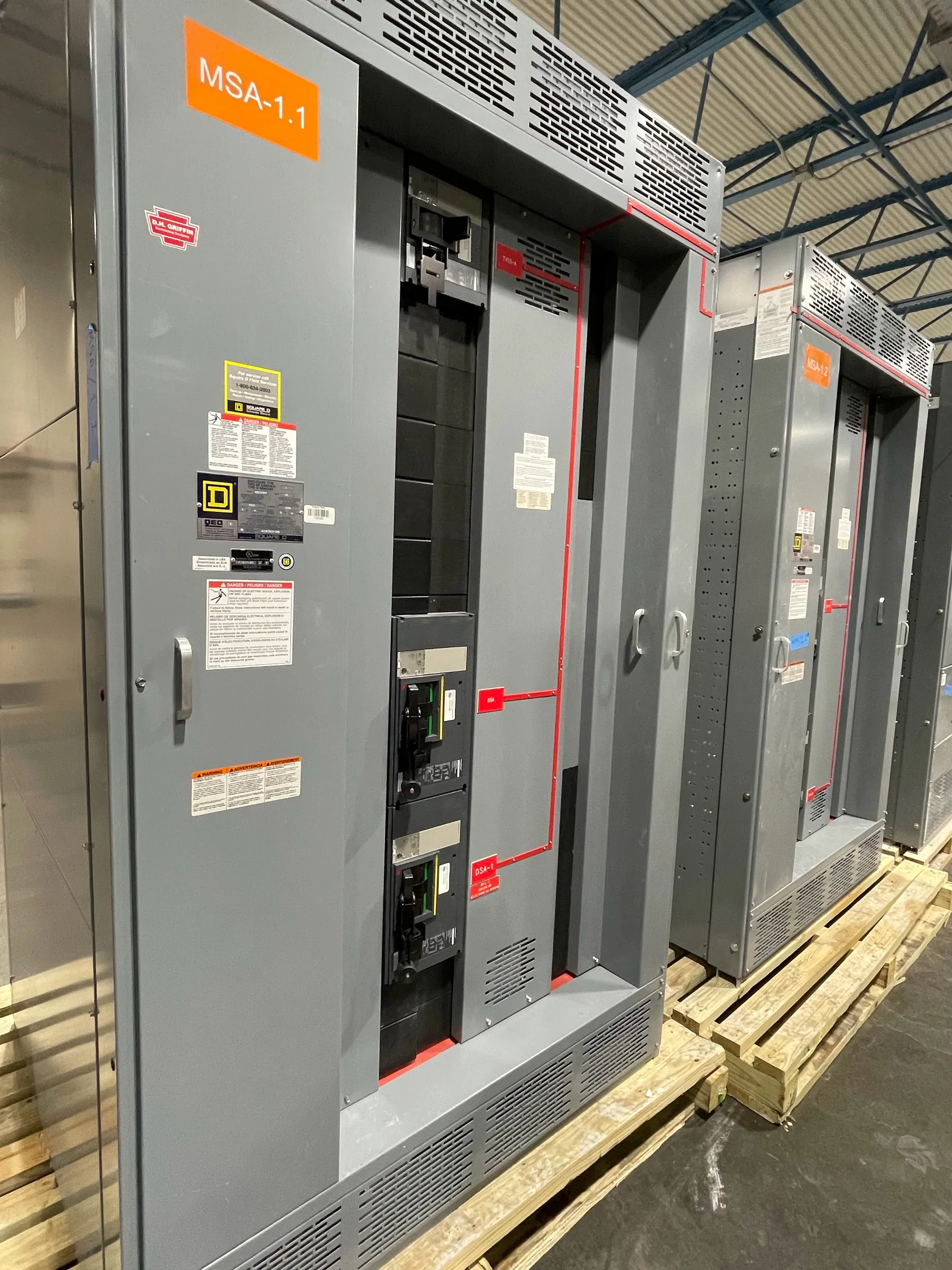
Pad-Mounted Switchgear Planning for Boulder City Projects
Pad-mounted switchgear brings switching and, depending on the selected assembly, protection functions into an outdoor enclosure near the equipment or service it supports. In Boulder City, the design should start with the project’s electrical one-line, site plan and defined utility interface—not with an assumed enclosure or standard arrangement. The intended function, system configuration and operating requirements determine which switching scheme and ratings are appropriate. Utility requirements and the project’s electrical engineer should be coordinated early, before the service design is released.
Site conditions also shape the installation. The location must accommodate the enclosure, its foundation, cable routes and the clearances required by the equipment design and applicable project requirements. Access for installation, inspection and future maintenance should be considered alongside vehicle routes, walls, landscaping and other site features. Conditions vary across commercial, industrial and municipal properties, so a location suitable on one parcel should not be treated as a template for another.
Outdoor Enclosure, Foundation and Site Exposure
The enclosure protects electrical components from outdoor exposure, but its construction and environmental provisions must suit the actual site. Project teams should identify exposure to sun, dust, moisture, irrigation overspray, corrosive conditions and potential physical impact. These details inform enclosure material, finish, access arrangements and any project-specific environmental requirements. Avoid assuming that an outdoor designation alone addresses every site condition.
Foundation design is a related but separate coordination item. The civil and electrical teams should establish the pad’s location, dimensions, elevation, loading basis and provisions for incoming and outgoing conduits using the selected equipment’s approved arrangement. Drainage and finished grade matter: water should not be directed toward cable openings or allowed to collect where it could compromise access or the installation. Final foundation details require review against the equipment drawings and site conditions.
Cable Entry and Conduit Coordination
Conduit entry locations and cable paths need to be resolved before the pad and surrounding civil work are finalized. The number and arrangement of feeders, conductor sizes, bending space and the selected switchgear configuration all influence the cable compartment layout. A mismatch between field-installed conduits and the equipment’s entry provisions can complicate installation and may require design changes. Coordinate conduit plans with the manufacturer’s project drawings rather than relying on a generic footprint.
Routing should also account for separation, bend space, pulling access and the transition between underground duct banks and the enclosure. The design team should confirm which cables enter or leave each compartment, how spare conduits are handled and whether future circuits are part of the scope. Those decisions affect both the enclosure layout and the foundation plan.
Utility Interface, Metering and Grounding
For a Boulder City project, define the utility interface before releasing the service design. Confirm the service arrangement, ownership boundary, switching responsibilities and required connection points with the serving utility and project team. The utility’s applicable requirements are project-specific; they should not be inferred from the city name or from equipment used elsewhere.
Metering needs the same early attention. Identify whether metering is utility-owned or customer-side, where it belongs in the service arrangement and what compartments, wiring provisions or access requirements apply. Grounding and bonding must be developed as part of the site electrical design, including the relationship among the switchgear, grounding electrode system, cable shields where applicable and other connected equipment. A qualified electrical engineer should coordinate these details with the utility and confirm the project design.
Ratings, Protection and Equipment Configuration
Specify ratings against the actual system and study conditions. Voltage, continuous current, short-circuit capability and switching or interrupting duties are distinct considerations; a product rating does not by itself establish suitability for a particular system. The required configuration depends on the one-line, available fault current, protective-device coordination and the intended switching function. These values and selections require engineering review and confirmation for the project.
Protection choices may affect the number and type of ways, fuse or interrupter arrangements, control provisions and compartment layout. The design team should provide the latest one-line, load information, fault-current basis and protection criteria when requesting a quotation. Any required listing or standard applicability must be verified for the specific assembly and scope; UL 891 applies to applicable low-voltage switchboards and should not be assumed to cover pad-mounted switchgear.
Quotation Inputs and Manufacturing Coordination — Pad-Mounted Switchgear in Boulder City, NV
A useful quotation package includes the project location, system voltage and configuration, one-line diagram, utility interface requirements, metering criteria, preliminary site and conduit plans, environmental conditions, required ratings and preferred schedule. Include any operating or access constraints and identify the responsible utility contact or design authority when available. Clear inputs help the manufacturer evaluate the requested configuration and identify open coordination items; they do not substitute for final engineering review.
Our company manufactures new custom power-distribution equipment in the United States using all-American components. For Boulder City customers, equipment can ship from the U.S. manufacturer to the project location, with lead time dependent on the finalized scope and production requirements. Before release, review approved drawings against the utility interface, metering and grounding scheme, foundation, cable entry and equipment ratings. That coordinated review helps align the manufactured assembly with the project’s site and service design.