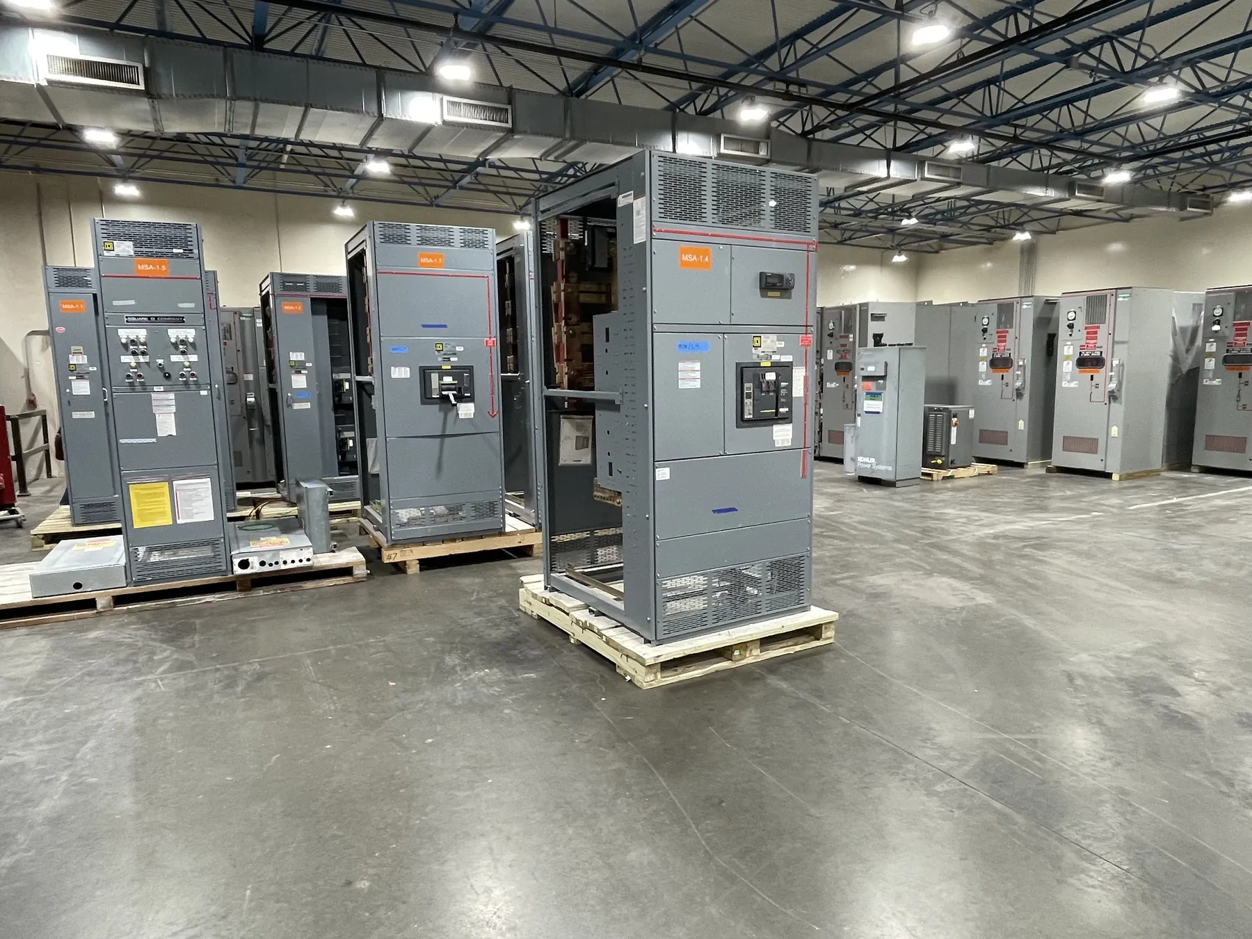
Motor Control Center Planning for Boulder City Facilities
A motor control center (MCC) brings motor starters and related control equipment together in a coordinated assembly. For a Boulder City project, the useful starting point is the facility’s motor schedule and electrical service—not a standard lineup assumed to fit every application. Pumps, fans, compressors, and other driven loads can differ in operating duty, starting method, control needs, and expected expansion. Those differences influence enclosure arrangement, unit selection, feeder protection, and the interfaces required at the site.
We manufacture new custom power-distribution equipment in the United States using all-American components. We can develop an MCC quotation around the project documents and requirements supplied by the customer. Before design release, the project’s electrical engineer and relevant site stakeholders should establish the intended service configuration and confirm that the proposed equipment suits the installation. Nevada projects can be served by nationwide shipment; shipping arrangements and site access should be considered alongside the equipment footprint and receiving plan.
Motor Starters, VFD Integration, and Control Interfaces
Starter selection depends on the motor and the process it serves. Across-the-line starters may suit some loads, while reduced-voltage starting or variable-frequency drives (VFDs) may be appropriate when starting behavior, process control, or system requirements call for them. The choice affects more than the motor unit: it can change heat dissipation, internal separation, feeder protection, control wiring, and the space needed for access and service.
For VFD sections, clarify whether drives are furnished as part of the MCC or supplied separately, and define responsibility for drive configuration, motor leads, bypass arrangements, and control connections. Identify required signals and communication interfaces, along with any project requirements for isolation or filtering. Drive selection and installation details must be evaluated against the motor, driven equipment, electrical system, and site conditions. These decisions should be coordinated by qualified engineering personnel rather than inferred from a product name or a single voltage value.
Short-Circuit Ratings and Feeder Protection — Motor Control Centers in Boulder City, NV
Short-circuit ratings describe an assembly’s ability to withstand or interrupt specified fault conditions under stated conditions. They are not the same as the system’s nominal voltage, and a rating cannot be chosen solely from the service voltage. The available fault current, protective-device characteristics, upstream equipment, and the applicable design basis all matter. Provide the project’s fault-current information and upstream protection details when requesting a quotation; the electrical engineer must confirm the required rating and protective coordination.
Each motor feeder also needs protection suited to its load and the governing project requirements. Confirm the intended starter type, motor data, overload approach, branch-circuit protective device, and any coordination objectives. Where an existing distribution system is involved, identify upstream and downstream devices so engineers can assess selectivity and interface constraints. Final ratings, device selections, and design details require review against the actual system and applicable code requirements.
Utility Interface, Metering, and Grounding for Boulder City Projects
Define the utility interface before releasing the service design. The project team should establish the service arrangement, available system information, point of connection, and responsibilities for utility-facing equipment. Metering requirements may depend on the service configuration and the responsible utility or project authority; identify meter location, compartment or instrument requirements, and any communication provisions early. Do not assume that a particular metering arrangement or utility approval applies without project-specific confirmation.
The grounding scheme also needs to be clear at the service and equipment interfaces. The engineer should document how grounding and bonding are handled, including the relationship between the MCC, service equipment, and facility grounding system. Provide drawings or written criteria that identify the intended neutral and grounding arrangement where applicable. This prevents a lineup from being quoted against an ambiguous interface and helps the design team coordinate the MCC with the broader electrical distribution system.
UL 845, Construction, and Maintenance Access
Ask whether UL 845 is required for the project’s motor control center and confirm the applicable specification and acceptance requirements. A standards reference should be checked against the actual product scope and procurement documents; it should not be treated as a blanket claim that every configuration is listed or suitable. Any required listing, construction detail, or documentation must be confirmed for the proposed assembly before commitment.
Maintenance access is a design input, not an afterthought. Share the available room dimensions, access direction, cable-entry preferences, nearby obstructions, and any operational constraints that affect placement or serviceability. Consider how doors, unit withdrawal or replacement, wiring access, and adjacent equipment affect the installation. Boulder City site conditions vary by facility, so the project team should verify environmental conditions and receiving constraints rather than rely on assumptions about a typical local installation.
Information for a Custom MCC Quotation
A useful quotation package includes the motor and load schedule, one-line diagram, control requirements, system voltage and frequency, available fault-current data, upstream protective devices, metering and grounding criteria, and any applicable specifications. Include enclosure and room information, cable-entry expectations, required options, and the requested standards or listing criteria. Flag items still awaiting engineering or utility confirmation so they can be identified as open design inputs.
With those details, the manufacturer can develop a proposed lineup and identify questions that need resolution before release. Ratings, listing status, dimensions, interfaces, and project suitability remain subject to document review and qualified engineering confirmation. Short lead times are supported, and new manufactured equipment can ship nationwide; timing and shipment details depend on the finalized scope and project requirements.