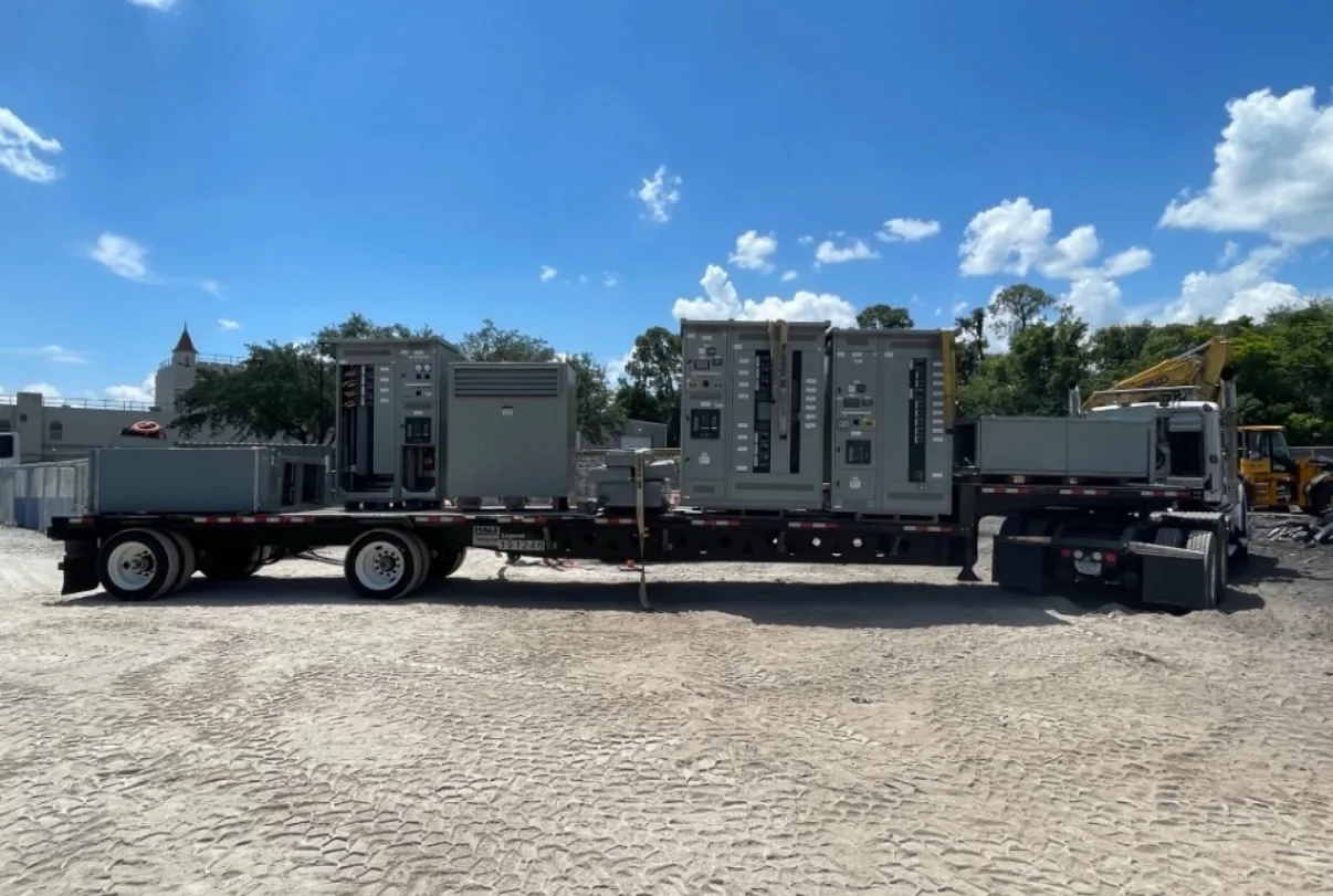
Metal-Enclosed Switchgear for Boulder City Projects
Metal-enclosed switchgear is an assembly of switching and protective devices housed in metal compartments. For a Boulder City project, selecting the enclosure is only one part of the service design: the incoming source, utility interface, metering arrangement, grounding method, protective devices and connected load all affect the configuration. A useful first step is to establish who owns each part of the electrical service and where the ownership boundary falls. That boundary influences how the incoming section, metering provisions and customer equipment are arranged.
Site conditions also matter. The equipment location, available working and service clearances, access route, indoor or outdoor exposure, and planned cable or bus connections should be reviewed before the lineup is released for manufacture. Nevada heat, dust and sun exposure can be relevant where equipment is installed outdoors or in a space with limited environmental control. The project team should define the actual conditions and enclosure requirements rather than assume a standard configuration will suit every site.
Choose Switching and Protection Around the Service
Switch-and-fuse arrangements and breaker-based configurations serve different design purposes. A switch with fuses can provide a means of disconnecting and protecting a circuit, with fuse characteristics selected for the application. A circuit breaker combines switching and overcurrent protection in a device whose trip functions and settings must be coordinated with the system. Neither choice is automatically preferable; available fault current, load characteristics, upstream and downstream protection, operating needs and the project’s maintenance approach all enter the decision.
For a quotation, identify the incoming source and voltage, the number and purpose of feeders, load information, the proposed protective-device types and any required metering or control provisions. The design team should also clarify whether the equipment serves a utility, facility, transformer or other interface. Preliminary descriptions are useful for budgeting, but final device selection and settings require qualified engineering review and coordination with the complete electrical system.
Fault Duty, Ratings and System Voltage
Fault-duty requirements are not interchangeable with normal operating load. The available fault current at the equipment location, protective-device clearing characteristics and the assembly’s applicable withstand or interrupting ratings must be evaluated together. A rating shown for a component does not, by itself, establish that the complete lineup is suitable for the installation. The system voltage and equipment ratings are also distinct: project documents should state the nominal system information and the required ratings separately.
Provide the latest available utility or system data, including the source configuration and fault-current information, for engineering review. If those details are not yet established, identify them as open items rather than treating a preliminary rating as final. Required ratings, product scope, listings and configuration must be confirmed for the actual design; a general description of metal-enclosed switchgear cannot determine suitability for a particular service.
Barriers, Grounding and Access Shape the Layout
Metal barriers separate compartments and help define how devices, bus and cable spaces are arranged. The required separation depends on the selected construction and project requirements. Discuss which components need individual compartments, how cable terminations will be reached, and whether maintenance or inspection access has constraints. The enclosure’s arrangement should support the intended installation without implying that barriers eliminate electrical hazards or replace site-specific safety controls.
Grounding details deserve early attention. The design should identify the grounding electrode and equipment-grounding arrangements, neutral treatment where applicable, and how the switchgear connects to the facility grounding system. Incoming and outgoing conductor entry, lug provisions, cable sizes and termination space should be established with the electrical engineer and installer. Access doors, removable panels, conduit locations and room clearances should likewise be checked against the site plan and equipment requirements.
Metal-Enclosed Is Not the Same as Metal-Clad — Metal-Enclosed Switchgear in Boulder City, NV
Metal-enclosed describes equipment housed in a metal enclosure; it should not be used as a synonym for metal-clad construction. Metal-clad switchgear has a more specific construction approach, including defined compartmentalization and separation features. The terms can indicate different equipment designs and application expectations, so procurement documents should name the intended construction and cite the project specification rather than rely on informal shorthand.
Confirm that the proposed product category, voltage class, device arrangement and required construction details match the engineer’s design. UL 891 applies to applicable low-voltage switchboards; it is not a blanket standard for all switchgear or for medium- or high-voltage products. Any applicable listing or standard must be verified for the particular assembly and scope instead of inferred from the product name.
Prepare a Complete Boulder City Quotation Package — Metal-Enclosed Switchgear in Boulder City, NV
A clear request should include one-line diagrams, service and system information, load and feeder schedules, utility interface requirements, metering details, grounding scheme, fault-duty data and the specified enclosure environment. Note the installation location, cable-entry direction, available space, access route and any known construction or commissioning constraints. If utility requirements or metering details are pending, identify the responsible party and expected design milestone so the quotation can distinguish confirmed scope from assumptions.
New custom equipment is manufactured in the United States using all-American components and can ship nationwide, including to Boulder City. Delivery planning should account for the project’s receiving access, unloading arrangements, site readiness and coordination with installation work; no schedule should be assumed until the equipment scope and project timing are reviewed. A complete, coordinated design package helps resolve interface questions before release and gives the manufacturer a sound basis for configuring the assembly.