Metal-Clad Switchgear for Boulder City Project Design
Metal-clad switchgear is a medium-voltage assembly arranged with grounded metal barriers separating major functional compartments. For a Boulder City facility, the design begins with the electrical service arrangement—not with a standard lineup selected from a catalog. The service source, required switching functions, available fault current, load characteristics, future expansion plans and site conditions all affect the configuration. A project team should also establish who owns each part of the service, where the utility interface falls, and how metering and grounding will be arranged before the service design is released. Those decisions can change compartment layouts, instrument-transformer requirements, cable entrances and the physical space needed for the lineup.
Compartmentalization and Withdrawable Breaker Choices — Metal-Clad Switchgear in Boulder City, NV
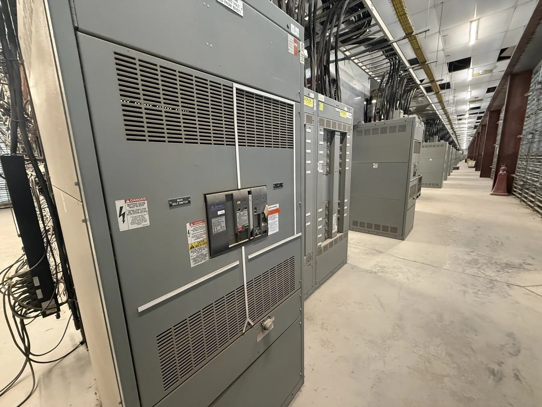
In metal-clad construction, barriers separate the bus, breaker, cable and low-voltage control areas as specified for the selected design. This separation helps limit exposure between compartments, but it does not eliminate electrical hazards or replace a project-specific safety evaluation. Withdrawable breakers are mounted on a mechanism that permits defined connected, test or disconnected positions, subject to the equipment design and operating instructions. That arrangement can support maintenance planning and breaker replacement, while adding requirements for compatible breaker designs, interlocks, racking provisions and sufficient working space. Engineers should identify whether the lineup needs incoming, feeder, tie or other breaker positions, and verify that the proposed breaker functions and compartment arrangement match the one-line diagram.
IEEE C37.20.2 and the Equipment Specification
IEEE C37.20.2 is the relevant standard to identify when specifying metal-clad switchgear within its scope. The project specification should state the applicable edition and define the equipment configuration, ratings, controls and other required features; the standard is not a substitute for complete project requirements. Confirm that the proposed assembly and its intended use fall within the standard’s scope, and have the responsible electrical engineer review the specification and exceptions. Do not assume that a reference to IEEE C37.20.2 alone establishes a particular listing, utility acceptance or suitability for every site condition. Voltage class, continuous-current and interrupting ratings, insulation requirements and other selections must be checked against system data and confirmed for the actual equipment.
Grounding, Metering and the Utility Interface
Before releasing a Boulder City service design, coordinate the utility’s point of connection, ownership boundary, service configuration and metering requirements with the project engineer and utility representatives. Confirm whether metering is utility-furnished or part of the specified assembly, along with the required instrument transformers, test provisions and compartment access. The grounding scheme must be defined in relation to the source and the facility’s grounding system, including how the switchgear enclosure, equipment grounding conductors and system grounding provisions are addressed. These are interconnected design choices: a change in the service arrangement or metering location can affect the lineup, cable routing and grounding details. Utility requirements and approvals must be verified for the specific project rather than presumed.
Protection, Relays and Coordination Inputs
Relay functions and settings should follow a coordinated protection study prepared by qualified project professionals using verified source and load information. Useful quotation and design inputs include the one-line diagram, nominal system voltage, available fault-current data, transformer details, load and motor information, protective-device data, metering requirements and the intended operating arrangement. The study should consider coordination with upstream and downstream devices, equipment withstand and interrupting capabilities, and the consequences of alternate source or tie configurations where applicable. Protection choices may affect current transformers, voltage transformers, relays, control power and wiring. Settings cannot be responsibly selected from a location name or a general equipment description; they require engineering analysis and confirmation against actual system conditions.
Quotation, Site Conditions and Delivery Planning
A complete request for quotation should describe the required lineup functions, ratings, applicable IEEE standard and edition, drawings, control and communication needs, metering interface, cable entry, indoor or outdoor installation conditions and any known space or access constraints. Boulder City site details—such as equipment-room dimensions, environmental exposure, route to the installation area and available lifting access—should be reviewed early because they may influence enclosure choices, shipping sections and installation planning. Ratings are not the same as system voltage, and all ratings, listings and project-specific details require confirmation by the responsible engineers and manufacturer. New custom equipment is manufactured in the United States using all-American components, with short lead times supported and shipping available nationwide; the schedule and configuration are confirmed for each order.