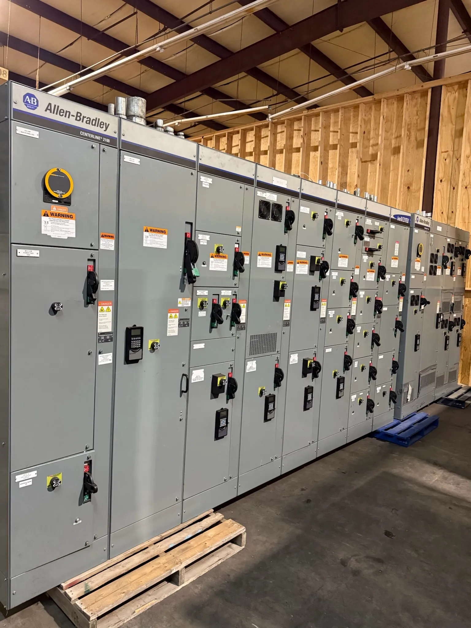
Data Center Switchgear Planning for Boulder City Projects
Data center distribution equipment has to fit the facility’s power architecture, operating priorities and maintenance plan—not just a one-line diagram. For a Boulder City project, establish how utility service, standby generation, uninterruptible power supply (UPS) equipment and downstream distribution connect before specifying the switchgear. Those interfaces shape the equipment lineup, protective-device coordination, metering provisions and space needed for future work.
We manufacture new custom switchgear and power-distribution equipment in the United States using all-American components, and ship nationwide, including to Nevada. Early project information helps determine whether a proposed lineup can be engineered to suit the site and its electrical requirements. Equipment ratings, applicable listings and final design details must be confirmed for the specific project; a product description alone cannot establish suitability.
Define Redundant Paths and Source Transfer
Redundancy depends on the complete electrical arrangement. The design team should identify normal and alternate sources, the intended boundaries between power paths, and which loads may be served by each path. That review can reveal whether the switchgear needs separate sections, source-selection equipment, tie provisions, or physical and control separation. The right arrangement depends on the facility’s reliability objectives and operating sequence, not simply on adding another breaker.
Document how utility, generator and UPS interfaces are intended to work, including the source conditions that initiate a transfer and the conditions that permit return to normal supply. Confirm which equipment performs each function and where control responsibility resides. Switchgear can provide switching and distribution functions, but it does not by itself guarantee uninterrupted power or determine the behavior of a complete backup system.
Set the Utility, Metering and Grounding Boundaries
Before releasing the service design, define the utility interface with the project engineer and serving utility. Confirm the service arrangement, available fault-current information, service equipment boundaries and metering requirements. Metering location and configuration can affect compartment planning, wiring provisions and the division of responsibility between utility-facing and customer equipment. Utility requirements are project-specific and should be verified rather than assumed from a general equipment description.
Grounding and bonding details also need to be resolved across the service, generator, UPS and distribution systems. The design team should establish the grounding scheme and identify how source configurations affect it. Incomplete or conflicting assumptions can complicate equipment connections and protection design. Final decisions require qualified electrical engineering review using applicable project documents and site conditions.
Coordinate Protection Across Utility, UPS and Generator Sources
Selective coordination is a system-level design task: protective devices should be evaluated across the relevant operating modes, not only with utility power available. Generator fault characteristics and UPS operating behavior may differ from normal service conditions. The engineer should review applicable fault-current data, device characteristics, settings and the intended source combinations to determine whether the proposed coordination approach meets project requirements.
Switchgear ratings must be considered in context. A voltage rating is not the same as a system’s nominal voltage, and ratings, interrupting capabilities, device selections and enclosure details must be checked against the actual design. UL 891 applies to applicable low-voltage switchboards; it should not be treated as a blanket standard for every switchgear assembly or as a claim that a particular product is listed. Confirm the required construction and listing status for the specified equipment.
Make Bypass and Maintenance Sequences Explicit
A maintainable bypass sequence should be drawn and reviewed before equipment is released. Identify the equipment being bypassed, the source and load connections involved, the intended isolation boundaries, and the controls or interlocks required by the design. Consider how the sequence affects redundancy: a bypass arrangement may support maintenance, but its configuration can also create a temporary operating state with fewer independent paths.
Document the expected sequence and responsibilities in project engineering and operating materials. Physical access, cable routing, room layout and coordination with UPS or generator vendors can affect whether the intended arrangement is practical. Do not rely on a generic sequence to establish safe operation; qualified personnel must review the complete design, procedures and site conditions.
Prepare a Useful Boulder City Switchgear Quotation Request
For a focused quotation, provide the current one-line diagram, service and system voltage information, utility interface and metering requirements, available fault-current data, source-transfer concept, grounding approach, load and feeder schedule, and the preferred lineup location and access constraints. Include UPS and generator interface details, protection or coordination criteria, bypass requirements, environmental conditions, and any required specifications or listing expectations. Identify which project details remain provisional so they can be confirmed during engineering review.
Boulder City delivery planning should account for the actual site, receiving arrangements, equipment access and construction schedule. We can discuss manufacturing and shipment requirements for Nevada projects, but timing depends on the finalized scope and project coordination. Supplying complete, consistent design inputs early helps the team evaluate equipment configuration and avoid treating unverified ratings or interfaces as settled decisions.