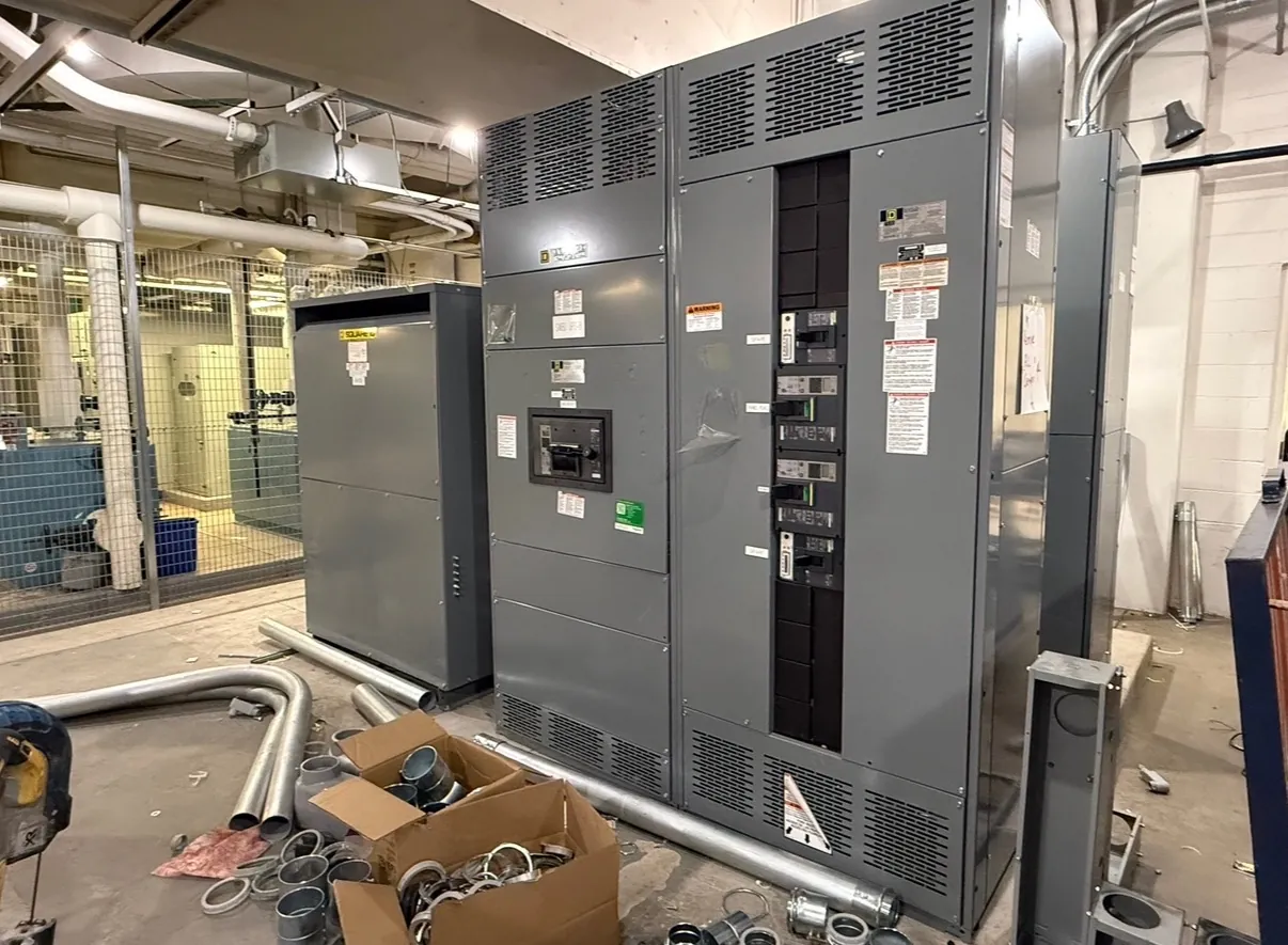
Selective Coordination Definition for Power-Distribution Systems
Selective coordination is the arrangement of overcurrent protective devices so that, when a fault occurs, the device closest to that fault interrupts it while upstream devices remain closed. The goal is to limit an interruption to the affected branch or section rather than unnecessarily disconnecting a larger portion of the electrical system. The phrase “closest device” describes its position in the protective-device sequence, not physical distance from a worker or a promise that every fault will be isolated by one particular device.
Coordination must be verified for the intended range of fault currents and operating conditions. If a device’s response overlaps with that of an upstream device, both may operate for some faults. A design therefore cannot be called selectively coordinated based on a general description of the equipment, a single setting, or the presence of circuit breakers alone.
How Selective Coordination Relates to Protection
Overcurrent protection addresses conditions such as overloads and short circuits by interrupting current when a protective device operates. Selective coordination is about the relationship among those devices: which one responds first, and whether the others remain closed. It does not mean that faults are prevented, that equipment is immune to damage, or that the rest of a system can never experience an interruption.
“Discrimination” is sometimes used to describe the same general objective of distinguishing the faulted circuit from upstream circuits. The exact terminology and required performance depend on the project, applicable codes, specifications, and engineering criteria. Coordination also differs from interrupting rating. An interrupting rating concerns a device’s ability to interrupt available fault current under stated conditions; it does not, by itself, establish selective coordination with another device.
What Engineers Verify Across the Device Sequence
Engineers evaluate protective-device characteristics throughout the path from the source to downstream loads. Relevant details can include the device type and model, trip-unit characteristics, adjustable settings, fuse characteristics where applicable, and the available short-circuit current at each point. Time-current information helps show how devices are expected to respond at different current levels, but curves and published tables must be applied within their stated limits and tolerances.
The review should consider the intended system configuration, not just a simplified one-line diagram. Source or transformer information, conductor and equipment impedances, alternate sources, tie breakers, and normal or emergency arrangements may affect the fault-current conditions or which devices are in series. A change in a breaker, trip unit, setting, source, or distribution path can alter the coordination result and may require the analysis to be revisited.
Ranges, Tradeoffs, and Practical Limits
Coordination is usually demonstrated over a defined current range, rather than assumed for every conceivable condition. At lower currents, one device may operate before another; at higher currents, device behavior can become more complex, and manufacturer-specific data or engineering methods may be needed. A selective-coordination claim should identify the relevant device combination, configuration, and range instead of implying unlimited selectivity.
There can be tradeoffs among coordination, protective response, equipment withstand capability, and system requirements. Adjusting a trip characteristic to improve separation between devices may affect how quickly a fault is cleared or whether the equipment can withstand the resulting conditions. Engineers must assess these factors together using site information and suitable device data. No single setting is universally appropriate for all switchboards or installations.
Applying the Definition to Custom Switchboards
In a custom low-voltage switchboard, coordination depends on the specified protective devices and the larger electrical system into which the board will be installed. The switchboard manufacturer can use the project’s approved device selections and documented design requirements when configuring the assembly, but the board alone cannot establish coordination for the entire distribution system. Upstream and downstream equipment, field connections, sources, and final settings may be outside the assembly’s scope.
UL 891 applies to applicable low-voltage switchboards; it should not be treated as a coordination determination or as a standard covering every kind of switchgear. Product ratings, any applicable listing, and project-specific details require confirmation for the particular equipment and intended use. Selective coordination is an engineering result, not an automatic feature conveyed by a product label.
Information Needed for a Coordination Review
For a quotation or engineering review, useful inputs include the one-line diagram, source and transformer data, available fault-current information, the proposed protective-device schedule, operating modes, and the project’s coordination criteria. Identify any required backup or emergency sources, tie configurations, and loads for which continuity is especially important. If some information is preliminary, mark it clearly so assumptions can be distinguished from confirmed design data.
A U.S. manufacturer producing new custom power-distribution equipment can build to confirmed project specifications and ship nationwide, including to Nevada. Shipping location does not determine selective coordination: the final assessment depends on qualified engineering review of the installation and the complete protective-device chain. Changes made after design review should be communicated so their effects can be evaluated before the system is placed in service.