Electrical Metering: What the Term Means
Electrical metering is the measurement and recording of electrical quantities in a power system. Depending on the meter and its configuration, those quantities may include voltage, current, power, energy, frequency, and power factor. A meter turns electrical signals into readings that people or control systems can use to understand consumption, verify operating conditions, allocate costs, or monitor equipment. The word “metering” describes this measurement function; it does not by itself identify who owns the meter, what it measures, or whether it meets a utility’s requirements.
Metering may be installed at a service entrance, a distribution board, a feeder, or an individual load. Its purpose and location shape the design. A service meter commonly supports utility billing, while meters downstream of the service can help a facility track energy use among departments, tenants, or processes. These functions are related, but the instruments, data interfaces, access rules, and approval processes may differ.
Utility Metering and Customer Metering
Utility metering is used by an electric utility to measure energy delivered at a defined point for billing or other utility purposes. The utility generally establishes the applicable meter type, metering arrangement, communication requirements, and physical interface. Requirements can vary by utility, service configuration, and jurisdiction, so a meter or metering compartment that suits one project should not be assumed acceptable for another.
Customer metering is installed or used by the facility owner or operator to observe electrical use within the customer’s system. It may support energy management, operational analysis, tenant allocation, or equipment monitoring. Customer meters do not automatically replace the utility’s billing meter, and their readings may not be suitable for billing or settlement without additional requirements. Clearly identifying the intended use prevents confusion between a monitoring point and a revenue metering point.
Some installations include both functions. In that case, the service entrance arrangement must provide the interfaces and space required by the utility while also accommodating the owner’s monitoring objectives. Meter access, wiring paths, enclosure layout, communications, and responsibility for furnishing or maintaining each component should be resolved during design coordination.
Direct Measurement and Instrument Transformers
A meter can measure circuit quantities directly when the meter and circuit are compatible with the application. In other arrangements, instrument transformers scale electrical signals for the meter. Current transformers (CTs) provide a reduced current signal proportional to primary current; potential transformers (PTs), also called voltage transformers in many contexts, provide a reduced voltage signal. The meter uses these inputs to calculate or display quantities such as energy and demand.
Transformer selection is not simply a matter of matching a number on a meter. The design must consider the circuit’s voltage and current, expected operating range, accuracy needs, burden, wiring arrangement, meter input requirements, and the intended measurement purpose. CT ratio and polarity, PT ratio and phase relationships, and the meter’s configuration affect whether readings are meaningful. Utility revenue metering may have specific instrument-transformer and installation requirements that differ from customer monitoring.
Instrument-transformer circuits also introduce design and maintenance considerations. Secondary wiring, terminal arrangements, grounding, enclosure space, and provisions for testing or isolation must be coordinated with the meter and applicable project requirements. These details should be reviewed by qualified electrical professionals; a generic diagram cannot establish a suitable arrangement for every system.
Readings, Ratings, and Measurement Boundaries
Voltage and current are electrical quantities; kilowatts represent real power, while kilowatt-hours represent energy used over time. Other readings may include reactive power, apparent power, power factor, demand, or frequency. A display’s available values depend on the meter’s capabilities, wiring configuration, programmed settings, and connected inputs. A meter that shows energy consumption does not necessarily provide the detail or accuracy needed for every operational or billing purpose.
Meter ratings and system voltage are related but not interchangeable. A product’s rating describes a specified equipment limit or capability under defined conditions; it does not, by itself, establish the voltage of the facility system or confirm that the meter is suitable for a particular installation. Likewise, a meter’s measurement range does not determine the rating of the switchboard or other distribution equipment. Ratings, listings, and compatibility must be confirmed for the actual product and application.
Metering Interfaces in Switchboards
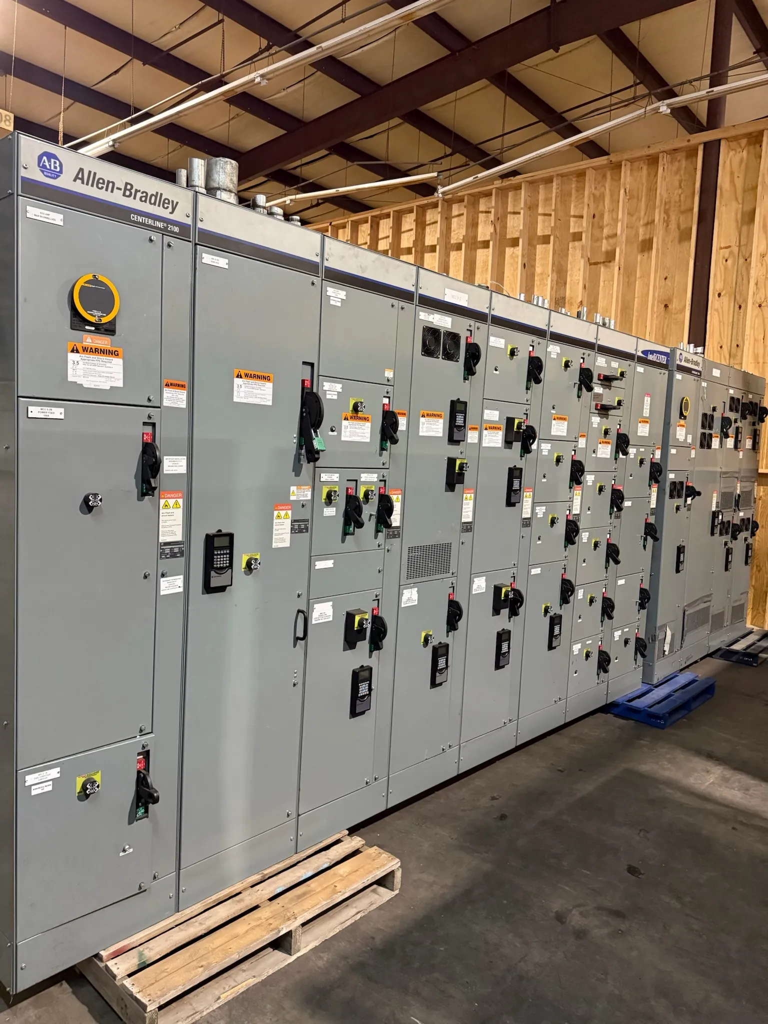
When metering is incorporated into a switchboard or other distribution assembly, the design must account for more than the meter face. Relevant choices can include the measurement point, direct or transformer-based inputs, meter mounting, CT provisions, voltage-sensing connections, communications, and separation of utility and customer functions. A specified interface may also affect compartment arrangement, wire routing, access, and coordination with protective devices.
For a custom equipment quotation, useful inputs include the service and distribution one-line diagram, system voltage and phase, available fault information, intended metering purpose, required measured quantities, utility metering criteria, and any preferred communications protocol or monitoring platform. Where instrument transformers are involved, their required ratios and accuracy criteria should be provided or developed with the project engineer and utility as applicable. Incomplete or conflicting inputs can change the proposed layout and require clarification before equipment details are finalized.
Coordination Before Equipment Is Finalized
Metering design should be coordinated among the owner, electrical engineer, equipment manufacturer, metering provider, and serving utility when utility-controlled metering is involved. Confirm who supplies each meter and transformer, who programs or commissions devices, how data will be used, and which party approves the arrangement. Also verify physical constraints at the installation site, including available equipment space, conduit routes, environmental conditions, and access requirements.
For Nevada facilities, the specific serving utility and site conditions matter; statewide assumptions are not a substitute for project review. A manufacturer can use the approved drawings and defined requirements to build new distribution equipment with the specified metering provisions. Final suitability depends on engineering review, utility coordination where required, and confirmation that the selected equipment and interfaces match the project.