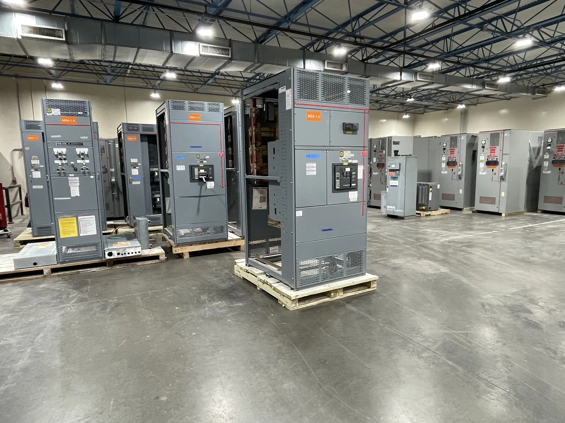
Ground-Fault Protection in Switchgear and Distribution Systems
Ground-fault protection detects electrical current flowing along an unintended path to ground or to grounded metal. A fault can occur when insulation is damaged, a conductor contacts an enclosure, or moisture or contamination creates a conductive path. Depending on the system and equipment, a protective device may sound an alarm, open a circuit, or provide both functions. Its purpose is to respond to a condition the system’s ordinary overcurrent protection may not detect quickly enough.
The term describes a protective function, not a single device or a complete grounding design. In a switchboard or switchgear assembly, ground-fault sensing and response are selected to suit the electrical system, the protected circuits, and the project’s operating requirements. The details need to be established by qualified electrical professionals using system information and site conditions.
How Ground-Fault Detection Identifies Current to Ground
Many systems detect a ground fault by measuring whether current leaving a circuit is balanced by current returning through its intended conductors. Sensors may monitor phase conductors together, or a protection scheme may use other sensing arrangements appropriate to the system. If the measured imbalance exceeds the configured response criteria, the protective equipment can initiate an alarm or a trip signal.
Sensor location matters. A device intended to protect a feeder must monitor the conductors associated with that feeder, and the arrangement must account for the system’s neutral conductor where one is present. Incorrect placement or an unsuitable sensing scheme can cause missed detection or unwanted operation. The design also has to account for normal leakage current and other system characteristics that affect measurement.
Ground-Fault Protection Is Not Grounding or Bonding
Grounding and bonding establish electrical connections; ground-fault protection detects a condition and prompts a response. System grounding connects a point in the electrical system, commonly a neutral point when applicable, to ground according to the design. Bonding connects conductive equipment and enclosures so they are electrically connected as required. These arrangements help define fault-current paths and system behavior, but they do not themselves detect a fault or open a circuit.
An equipment grounding conductor is part of the fault-current path. It is not ordinarily the same thing as the grounded neutral conductor, and the two have distinct roles. Their connections and separation depend on the system configuration and installation location. Treating a grounding conductor, a neutral, and a ground-fault sensor as interchangeable can lead to an incorrect design. Protection settings cannot compensate for an improperly designed or installed grounding and bonding system.
Protective Devices, Alarms, and Related Terms
Ground-fault protection equipment can include sensors, protective relays, trip units, circuit breakers, and alarm interfaces. The sensing element identifies a condition; the protective logic determines whether that condition meets the response criteria; and an interrupting device, if specified, opens the circuit. An alarm-only function reports a detected condition without necessarily disconnecting power. The project documents should make clear which response is required and which device acts on it.
Ground-fault protection is not synonymous with ground-fault circuit-interrupter protection. GFCI devices are commonly associated with personnel protection in particular applications, while switchgear ground-fault protection may serve different equipment and system objectives. Nor is ground-fault protection identical to overcurrent protection: a phase-to-ground fault may produce current that does not promptly reach an overcurrent device’s operating threshold. The required protection depends on the application, governing requirements, and engineered design.
Coordination and Switchboard Design Choices
On systems with multiple protective devices, engineers consider coordination: which device should respond to a fault and how much of the distribution system should be interrupted. Sensor location, pickup criteria, time delays, breaker characteristics, and downstream protection all influence that outcome. Settings that improve selectivity in one part of a system may affect clearing time or operation elsewhere. These choices require review of the system design and applicable requirements; they should not be inferred from a generic equipment description.
For low-voltage switchboards, ground-fault functions may be integrated with a breaker trip unit or provided through a separate relay and associated equipment. Available functions and suitable configurations vary by product and application. UL 891 applies to applicable low-voltage switchboards; it should not be taken as a blanket standard for all switchgear or for medium- or high-voltage equipment. A product’s ratings, listing status, and scope must be confirmed for the specific assembly and project.
Information Needed to Specify Ground-Fault Protection
For a new custom distribution assembly, useful quotation and engineering inputs include the one-line diagram, system voltage, phase and neutral arrangement, grounding method, available fault-current information, feeder and main-device details, and the intended alarm or trip response. The specification should identify which portions of the system need protection and provide coordination requirements or study information when available. Facility operating needs, such as the consequences of interrupting a main or feeder, also inform the design.
These details help determine compatible sensing, control, and interrupting equipment; they do not establish a final design by themselves. Ratings are not the same as system voltage, and ratings, listings, device compatibility, and project requirements need confirmation. A U.S. manufacturer building new switchgear or power-distribution equipment can review the specified interfaces and assembly scope, but final protection decisions require qualified engineering review of the complete system and installation conditions.