Feeder Definition for Distribution-System Planning
A feeder is a circuit that carries electrical power from a source or distribution point to downstream distribution equipment or loads. In a facility, a feeder may connect a service or transformer to a switchboard, connect one switchboard to another, or supply a panelboard or substantial piece of equipment. The term describes the circuit’s role in the system, not a single conductor type, voltage, physical route, or protective-device arrangement.
Feeders form the links between the point where power is distributed and the places where it is further divided or used. A circuit that supplies a panelboard is generally a feeder up to that panelboard; circuits leaving the panelboard to serve branch loads are typically branch circuits. The exact boundary depends on the system arrangement and applicable design definitions. This distinction matters when engineers document equipment interfaces, conductor requirements, and protection.
How a Feeder Differs from a Branch Circuit
A branch circuit generally supplies utilization equipment or outlets from the final overcurrent device serving those loads. A feeder, by contrast, supplies downstream distribution equipment or a group of loads. For example, a feeder may run from a switchboard to a distribution panel, where separate branch circuits begin. A motor or other substantial load can also be served through an arrangement whose circuit classification must be determined from the actual design and applicable electrical rules.
These terms are not interchangeable labels for “large” and “small” wiring. Circuit function, protective-device location, equipment connections, and governing code definitions all affect classification. Clear one-line diagrams and equipment schedules help prevent a feeder from being mistaken for a branch circuit during design review, equipment specification, installation planning, or troubleshooting.
Conductors, Ampacity, and Installation Conditions
Feeder conductors must be selected for the expected load and the conditions in which they will be installed. Relevant considerations include load characteristics, conductor material and insulation, number of current-carrying conductors, ambient temperature, grouping, raceway or cable method, terminal temperature limitations, and allowable voltage drop where applicable. A conductor size cannot be established from the word “feeder” alone.
Route length and layout can influence conductor size, voltage performance, installation labor, and available space in raceways and equipment. The design also needs to account for the feeder’s termination points: conductor range, lug configuration, phase arrangement, neutral requirements, grounding provisions, and available bending space must match the selected equipment and field conditions. Final conductor selection and installation details require qualified engineering review against the project documents and applicable codes.
Voltage, Equipment Ratings, and Interfaces
System voltage identifies the electrical system’s operating voltage; an equipment or circuit rating is a separate limit or characteristic. These values should not be treated as synonyms. A feeder’s voltage and phase arrangement must be compatible with the source, downstream equipment, insulation requirements, and connected loads. The project must also establish the relevant current ratings and fault-duty requirements for each point in the distribution path.
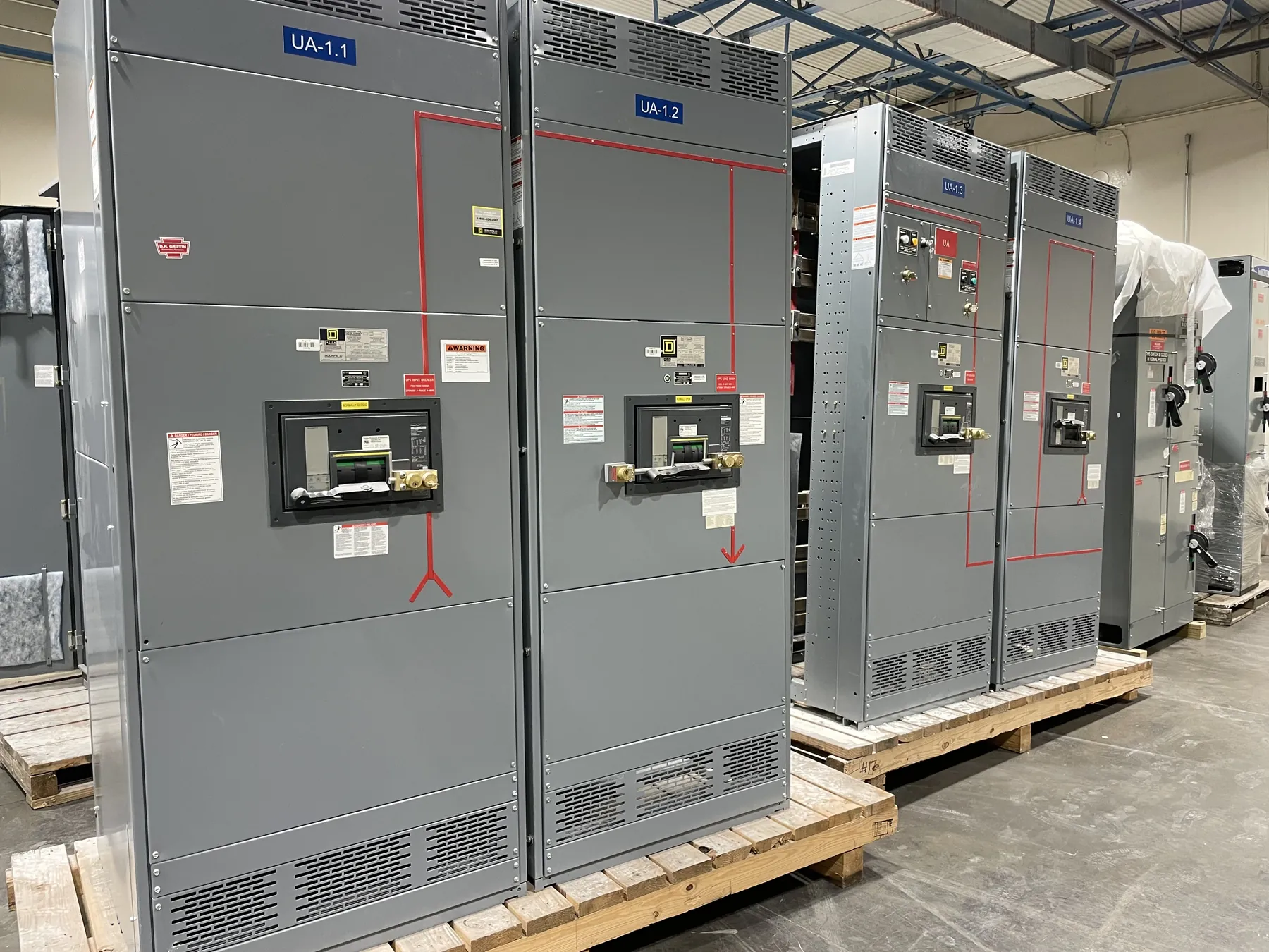
For custom switchboards and other distribution equipment, a feeder may enter or leave through a specific section, breaker, fuse arrangement, or terminal space. Layout depends on the one-line diagram, conductor entry direction, cable or bus connections, enclosure arrangement, and service access requirements. UL 891 applies to certain low-voltage switchboards when the product and configuration fall within its scope; it should not be assumed to cover every switchgear assembly or voltage class. Applicable ratings, listings, and construction details require confirmation for the actual product and project.
Feeder Protection and Coordination
Feeder protection is intended to address conditions such as overloads and short circuits, as determined by the system design and applicable requirements. The protective device must be considered alongside conductor ampacity, downstream equipment limits, available fault current, and the characteristics of connected loads. A device selected only by nominal current can be unsuitable if other system constraints are overlooked.
Coordination review considers how upstream and downstream protective devices respond to faults, with the objective defined by the project’s operational priorities and design requirements. The review may involve device curves, settings, equipment withstand limits, fault-current information, and the expected operating scenarios. Selective coordination is not automatic simply because devices have different ratings. Qualified engineers must evaluate the system and confirm device selection and settings; this page does not establish an operating procedure for energized equipment.
Information Needed to Specify a Feeder
For a switchgear or power-distribution quotation, useful inputs include the one-line diagram, system voltage and phase, feeder quantity and direction, load information, protective-device requirements, conductor material or connection method, and any specified fault-duty values. Also identify equipment location, enclosure and environmental conditions, cable-entry preferences, space constraints, and applicable project specifications. Missing or preliminary information should be identified rather than assumed.
These details help determine the required equipment arrangement and interfaces, but they do not replace site review or engineering. A U.S. manufacturer building new custom distribution equipment can use project documents to assess the requested configuration; ratings, listings, coordination, and final design remain subject to confirmation. For Nevada facilities, routing, ambient conditions, installation access, and site-specific requirements should be documented by the project team. Equipment can be manufactured in the United States and shipped nationwide, while the suitability of a particular feeder design depends on the verified project conditions.