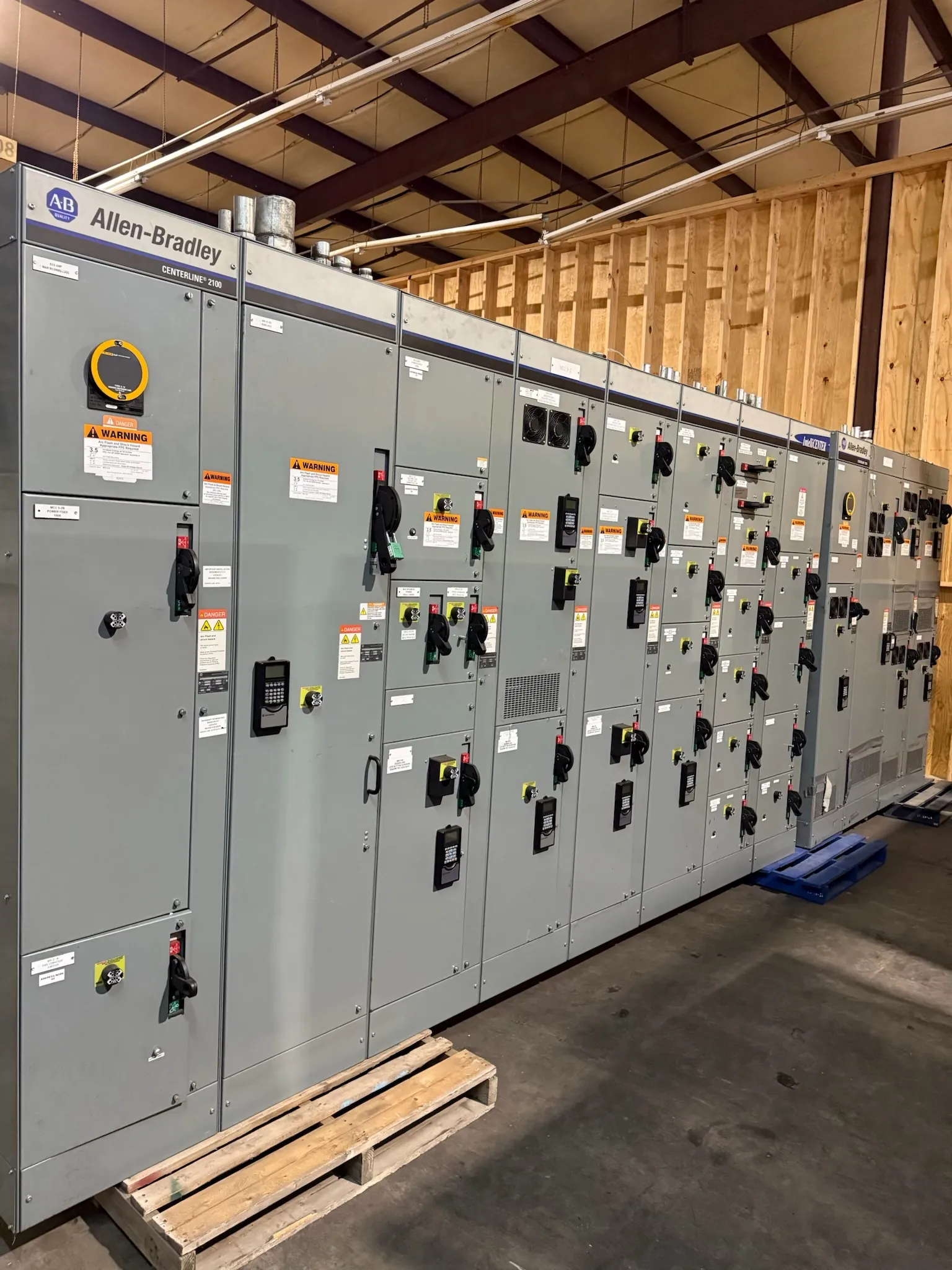
Busbar Definition for Switchgear and Power Distribution
A busbar is a conductive bar or group of bars that carries and distributes electrical power within equipment such as a switchboard, switchgear assembly, or panelboard. It provides a common electrical connection point for incoming power and connected circuits. Depending on the assembly’s design, busbars may be made from copper or aluminum and may be arranged as separate phase conductors, a neutral, and a grounding path. Their shape, material, size, spacing, and supports are selected for the equipment and its intended service—not by the word “busbar” alone.
In a custom low-voltage switchboard, busbars form part of the current-carrying system that connects devices and outgoing feeders. They are distinct from the breakers or switches that control and protect circuits, and from busway, which is a separate enclosed distribution system. A busbar may be internal to an assembly; its presence does not by itself establish the assembly’s voltage, current, fault rating, listing, or suitability for a particular installation.
Busbar Ampacity and the Conditions Behind It
Ampacity is the current a conductor can carry under specified conditions. A busbar’s usable ampacity depends on more than its cross-sectional area. Material conductivity, bar dimensions, orientation, spacing, surface finish, enclosure design, ambient temperature, ventilation, and the arrangement of nearby conductors can all affect heat dissipation. Connections and transitions between bars can also influence temperature performance.
For that reason, a bar’s standalone current-carrying capability should not be treated as the rating of the complete switchboard. The assembly’s marked ratings and construction details must be confirmed for the intended configuration and applicable requirements. A system’s operating voltage is also different from a busbar or assembly rating; both need to be specified and reviewed in context.
Designers may weigh compact dimensions against thermal performance, available space, and future circuit needs. Increasing conductor size or changing the arrangement can affect cost, enclosure dimensions, supports, and connection hardware. The appropriate choice is established through qualified engineering review of the assembly and installation conditions, not by choosing a bar based only on a nominal current figure.
Bracing, Supports, and Available Fault Current
Busbar supports hold conductors in position and help resist the mechanical forces that can occur during an electrical fault. The required bracing depends on the assembly’s design and the fault-current conditions it is intended to withstand. Conductor spacing, support placement, material, mounting method, and the geometry of bends and joints are relevant parts of the system. A busbar can have adequate ampacity yet still be unsuitable if its support arrangement is not appropriate for the expected fault duty.
Project review should therefore consider available fault current at the equipment location and the assembly’s corresponding short-circuit or withstand ratings, as applicable. Those values are not interchangeable with the busbar’s continuous-current rating. A qualified engineer must coordinate the equipment design with the electrical system and site information; field conditions or upstream changes can affect that evaluation.
Approved Busbar Connections and Interfaces
Where busbars join one another, connect to devices, or interface with incoming and outgoing conductors, the connection design matters. Contact surfaces, compatible materials, joint geometry, fasteners, and the specified assembly method all influence electrical continuity and mechanical integrity. Copper-to-aluminum interfaces, for example, require attention to material compatibility and the connection system selected for the application.
Use connections and components approved for the particular equipment design. Improvised drilling, substitutions, or changes to joint hardware can alter clearances, contact conditions, or structural performance and may affect applicable listing or ratings. Installation and maintenance work must follow the equipment manufacturer’s documentation and be handled by qualified personnel. Equipment-specific procedures should not be inferred from a general busbar definition.
Busbar Choices in a Custom Switchboard
Busbar decisions are coordinated with the assembly’s main devices, feeder layout, neutral and grounding configuration, enclosure, and expected expansion needs. A design with many outgoing circuits may require a different arrangement from one with a small number of large feeders. Space for cable entry and termination is also important: conductor bending room, lug positions, and access constraints can shape the layout without changing the project’s underlying electrical requirements.
For a quotation, useful inputs include the intended equipment type and application, system voltage, required continuous-current rating, available fault-current information, incoming and outgoing device details, conductor and termination preferences, neutral and grounding needs, enclosure and environmental conditions, and any applicable project specifications. These inputs help establish a reviewable scope; they do not substitute for engineering confirmation of the final design, ratings, or required listing.
Busbar Equipment for Nevada Projects
For facilities in Nevada, project planning should account for the actual equipment location and installation environment. Room dimensions, access routes, cable entry, ambient conditions, and the site’s electrical information can affect enclosure and busbar coordination. Shipping equipment to a Nevada site also calls for confirming receiving access, unloading arrangements, and the delivery point with the project team; these logistics do not establish a specific delivery date.
Custom switchgear and power-distribution equipment can be manufactured new in the United States using all-American components and shipped nationwide, including to Nevada. Product configuration, applicable ratings, listings, and project interfaces require confirmation for each order. The key point is that a busbar is not simply a metal strip sized by current: it is one engineered element within a coordinated electrical assembly.