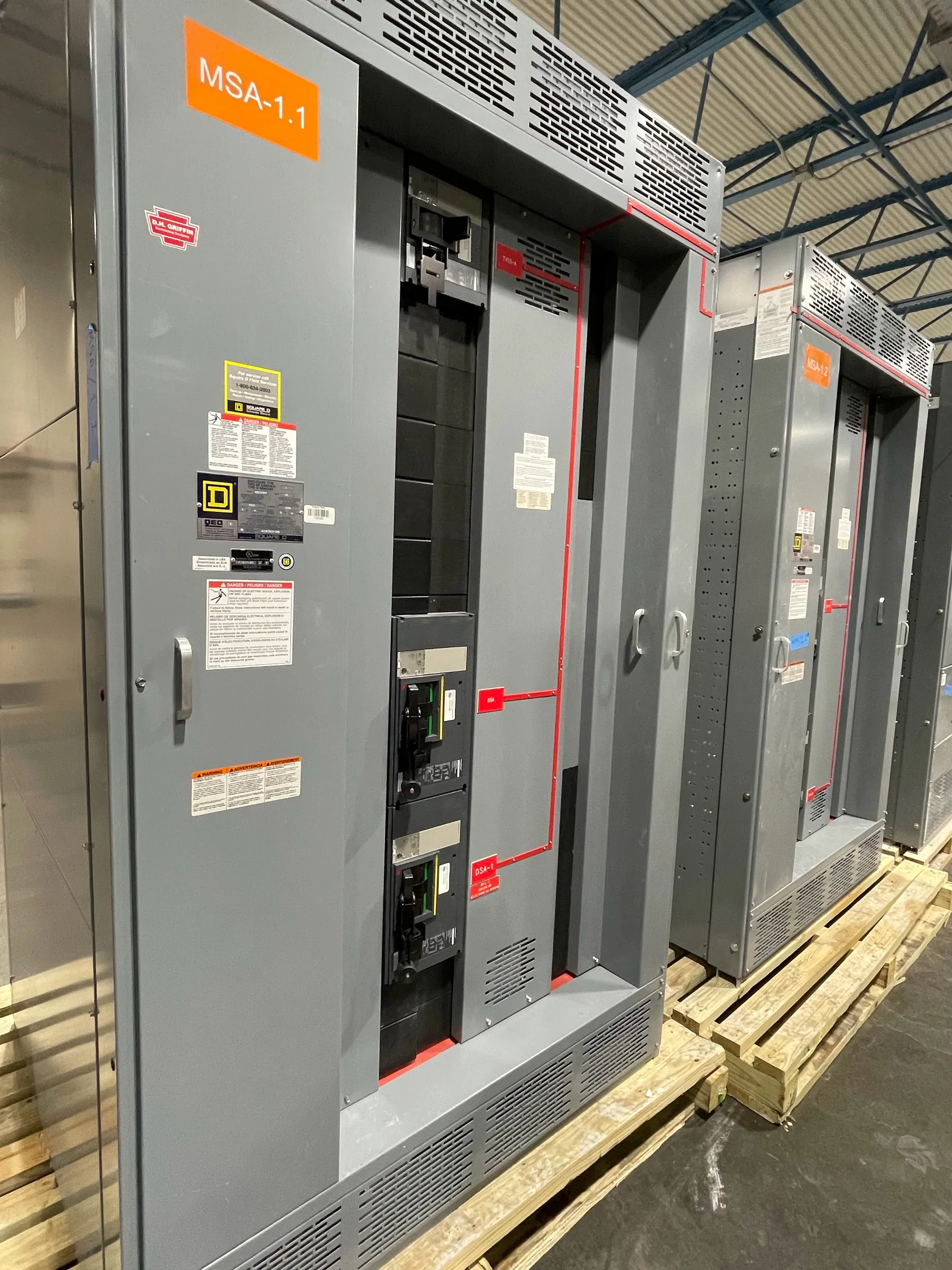
35 kV Class Equipment Starts With the System Voltage
For a facility planning 35 kV Class distribution, the first specification to confirm is the system’s nominal voltage and grounding arrangement—not a product label alone. The project engineer should establish the actual operating voltage, whether the source is grounded or ungrounded, and how the equipment connects to the utility or upstream distribution system. A 35 kV Class designation identifies an equipment class; it does not, by itself, state the system voltage or prove that a particular assembly is suitable for the installation.
Equipment selection must account for the highest voltage the system may place across insulation, including relevant operating conditions and grounding behavior. The required rated maximum voltage must be checked against that system condition. Avoid treating nominal voltage, rated maximum voltage, and insulation level as interchangeable terms. They describe different aspects of the application, and the project’s qualified electrical engineer should verify that the selected equipment is appropriate for the complete system.
Verify Rated Maximum Voltage and Insulation Level Together
Insulation requirements are not established by the 35 kV Class label alone. The specification should identify the required insulation level and the applicable withstand requirements for the equipment and its interfaces. Those choices depend on the system design, exposure to switching or lightning transients, grounding, protection, and the equipment’s installation environment. The engineer should confirm the governing design criteria rather than assume a standard insulation level from nominal voltage.
Review insulation coordination across the full path: incoming connections, switching devices, bus, instrument transformers, cable terminations, surge-protection provisions, and outgoing feeders. Component ratings and interfaces must be compatible with the assembly and with one another. Cable type, termination arrangement, phase spacing, and enclosure configuration can affect the practical design. Any changes to these inputs during procurement should be reviewed by the design team before equipment details are finalized.
Establish Fault Duty and Protection Coordination
Fault duty is a separate selection check from system voltage and insulation level. The available short-circuit current at the proposed connection point, the system’s X/R characteristics where required, and the expected fault-clearing time inform the equipment’s required interrupting and withstand capabilities. The project engineer must determine these values from the system study and confirm that the proposed switching equipment and assembly are suitable for the duty.
Protection coordination should be evaluated across upstream and downstream devices. Relay functions, instrument-transformer ratios, trip arrangements, and clearing times can influence how the system responds to faults and how much thermal and mechanical stress equipment may experience. A coordination study may identify changes to protective-device selections or settings. Do not infer fault capability from a voltage class, enclosure appearance, or a component rating considered in isolation; confirm the complete proposed configuration.
Resolve Interfaces Before the Equipment Design Is Final
Medium-voltage equipment is often shaped by connection and site constraints as much as by the one-line diagram. Identify whether incoming and outgoing circuits use cable or another connection method, the cable entry direction, termination type, phase arrangement, and required access. Document interfaces to transformers, generators, utility equipment, and downstream distribution, including any metering or protection requirements. If the project involves parallel sources, transfer arrangements, or alternate operating configurations, those conditions belong in the engineering review.
Facility conditions also matter. Provide indoor or outdoor installation requirements, available footprint, access routes, ambient conditions, elevation, ventilation expectations, and exposure to dust, moisture, or corrosive influences as applicable. Seismic, enclosure, and accessibility requirements should be stated when they apply. These details help determine construction and layout, but they do not replace a site-specific engineering review. Nevada projects may have varied site and climate conditions; the equipment specification should describe the actual installation rather than rely on a general location assumption.
Prepare Complete Inputs for a 35 kV Class Quotation
A useful quotation package gives the manufacturer enough information to identify the intended scope without substituting assumptions for engineering decisions. Include the one-line diagram, system voltage and grounding, required rated maximum voltage and insulation level, available fault-duty information, protection and metering requirements, connection details, and installation conditions. Note required interfaces, operating modes, drawings, documentation, and any project-specific review points. If a value is preliminary or still under study, label it as such so it can be resolved before final design.
Clarify the requested equipment boundaries as well: what is included in the assembly, what is furnished by others, and how field connections will be made. Confirm dimensions and access constraints against the facility layout. These inputs support a more accurate design review and reduce the likelihood of late changes to terminations, protection, or arrangement. Final ratings, listings, and project details require confirmation for the specific configuration and application.
Choose Standards That Match the Equipment Type
Standards must be applied to the product they actually cover. UL 891 applies to applicable low-voltage switchboards; it is not a medium-voltage standard and should not be used to establish compliance for 35 kV Class switchgear. Do not assume that a standard or listing associated with one component applies to the complete medium-voltage assembly. The project team should identify the applicable standards, required documentation, and any listing expectations for the specific equipment and jurisdiction, then confirm them during engineering review.
Custom equipment is manufactured in the United States using all-American components and can be shipped nationwide, including to Nevada. Lead time depends on the confirmed design, components, scope, and production schedule; no specific delivery interval should be assumed before the project is reviewed. A qualified electrical engineer and the manufacturer should reconcile system data, fault duty, interfaces, and site conditions before equipment ratings and final configuration are accepted.