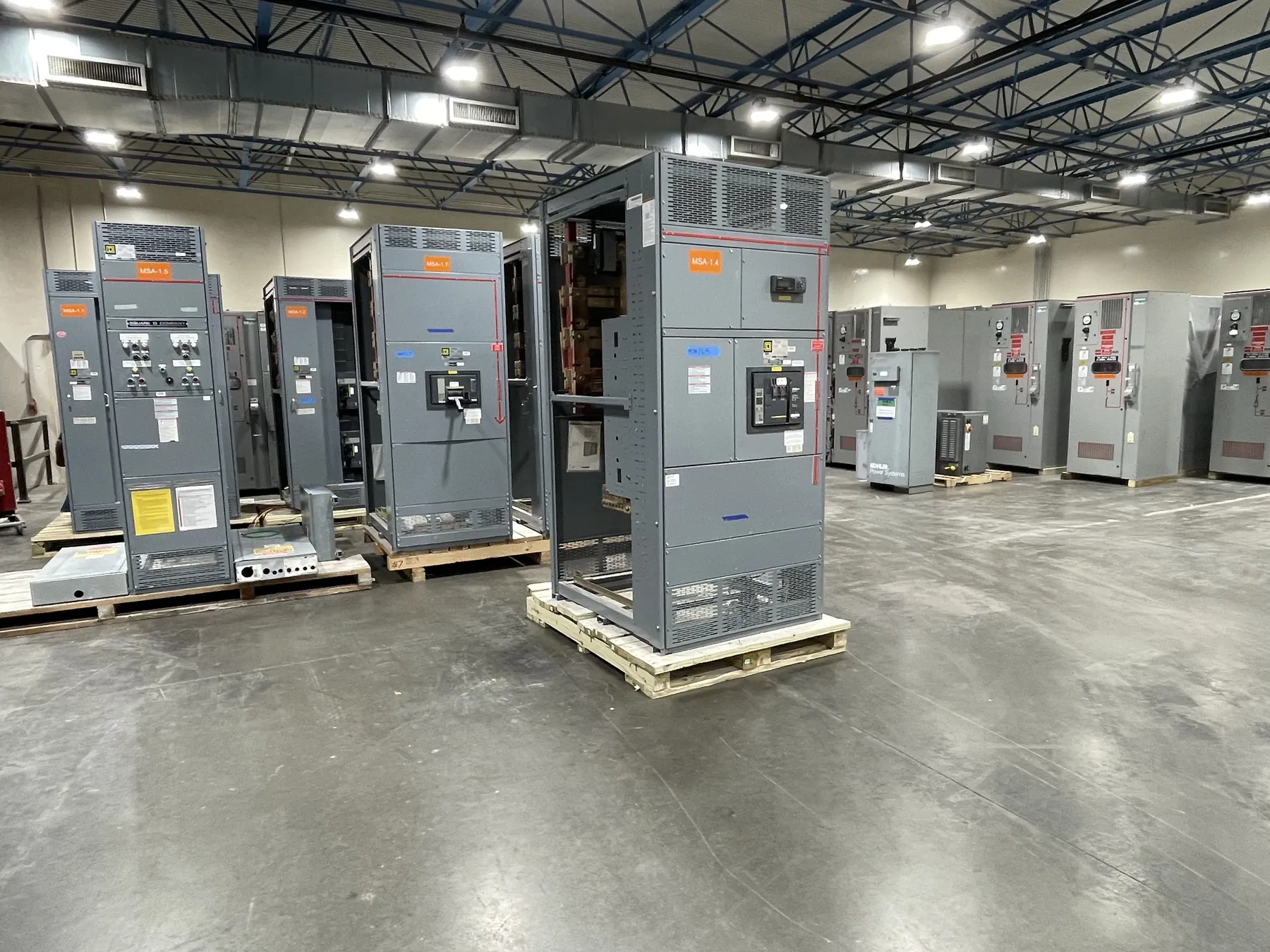
5 kV-Class Metal-Clad Switchgear for Medium-Voltage Systems
Metal-clad switchgear for a 5 kV class application is engineered around the electrical system it will serve, not selected by class designation alone. The design must match the system’s nominal voltage, maximum operating conditions, available fault current, insulation requirements, protection scheme, cable arrangement and installation environment. A 5 kV class label does not, by itself, establish that an assembly is suitable for a particular system or duty. Our U.S.-manufactured equipment uses all-American components, is built to order, and can ship to Nevada and other destinations nationwide. Configuration, ratings and schedule depend on the project requirements and final documentation.
Compartmentalization and Withdrawable Breakers — Metal-Clad Switchgear for 5 kV Class
Metal-clad construction separates major functional sections, such as the main bus, circuit breaker, cable connections and low-voltage control components, using grounded metal barriers as specified for the design. This arrangement helps define equipment interfaces and maintenance boundaries; it does not remove the need for qualified engineering, site-specific hazard evaluation or the operating instructions provided with the completed assembly.
Withdrawable breakers are installed in a dedicated compartment and connect to the switchgear through defined primary and secondary interfaces. Project choices may include breaker arrangement, control wiring, interlocking provisions, instrument transformers and auxiliary contacts. These choices affect the switchgear lineup, protection and control integration, and the space needed for installation and servicing. The approved drawings and equipment documentation must confirm the actual breaker type, compartment details, ratings and available options. Do not assume that a feature offered on one configuration is included in every 5 kV class lineup.
Nominal Voltage, Maximum Voltage and Insulation Level
Nominal system voltage describes the system’s designated operating voltage; equipment maximum voltage is a separate rating that defines the highest system voltage for which the equipment is designed. Neither should be inferred from the phrase “5 kV class.” The project team must verify the actual system voltage and ensure that the selected switchgear’s maximum voltage and insulation level are appropriate for the service conditions.
Insulation requirements relate to how the equipment withstands specified electrical stresses. They are distinct from continuous-current capability and interrupting duty. System grounding, switching conditions, installation environment and applicable design requirements can affect the information engineers need to establish the correct insulation selection. Confirm the equipment’s stated ratings in its documentation rather than relying on a class name or an informal description.
Interrupting Duty, Bus Ratings and Protection Coordination
Breaker interrupting duty must be evaluated against the available fault current at the equipment location and the characteristics of the electrical system. It is not interchangeable with a continuous-current rating, and it cannot be selected from nominal voltage alone. Engineers also need to review the switchgear short-circuit withstand capability and the relationship between the breaker, bus and connected equipment. The applicable ratings must be confirmed as a coordinated set for the specified configuration.
Relay coordination is a system-design task. Protective-device settings and time-current behavior should be assessed alongside upstream and downstream devices, fault conditions, transformer characteristics, connected loads and the consequences of interruption. Relay functions, instrument-transformer ratios and control interfaces should be identified in the project requirements. Final settings and protection decisions require qualified engineers with the relevant system data; they should not be assumed from a switchgear class or a preliminary quotation.
IEEE C37.20.2 and Cable Termination Interfaces
For metal-clad switchgear, the project should identify the applicable edition and requirements of IEEE C37.20.2 and confirm that the proposed assembly is designed and documented for the specified scope. Applicability depends on the equipment and project requirements; the standard should not be treated as evidence that every product option or system condition is covered. Confirm the applicable standard, ratings and documentation directly for the quoted configuration.
Cable terminations require particular attention because conductor type, size, quantity, routing, termination method and incoming or outgoing cable direction influence compartment layout and connection details. Engineers should provide the cable schedule and identify whether the installation uses top or bottom entry, required working space, cable support and any interface constraints. Termination requirements must be checked against the equipment drawings and the cable and accessory specifications.
Information Needed to Confirm a 5 kV Class Configuration
For a useful quotation and engineering review, provide the nominal system voltage, grounding method, available fault-current information, required continuous-current and interrupting ratings, lineup and feeder arrangement, protection and control requirements, cable details, installation location and applicable project standards. Include relevant site constraints such as room dimensions, access route, environmental conditions and connection orientation. These details help distinguish an appropriate design from one that merely carries the requested class label.
Before release for manufacture, review the approved equipment documentation for the actual configuration, ratings, interfaces and project-specific requirements. Documentation is the basis for confirming what the supplied assembly includes. Equipment ratings, listings and standard compliance must be verified for the specific design; they should not be presumed for all metal-clad switchgear. Final selection and integration depend on qualified engineering review and the conditions at the installation site.