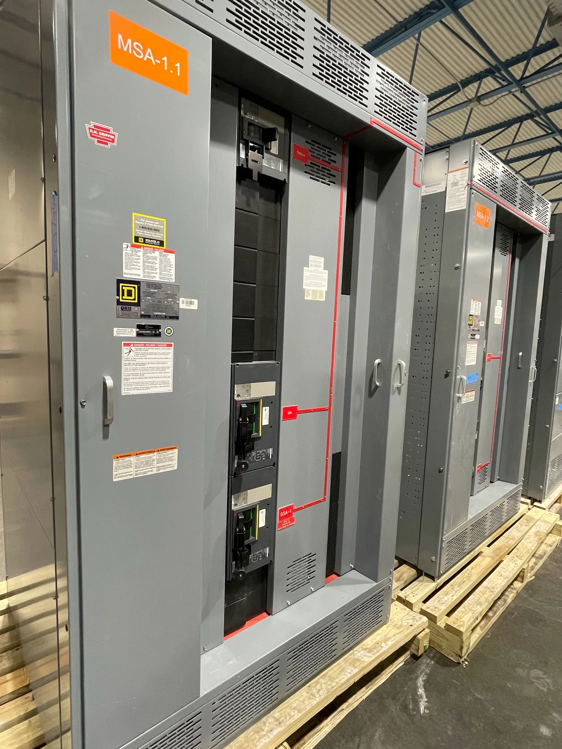
15 kV-Class Metal-Clad Switchgear: Selecting the Equipment Basis
Metal-clad switchgear for a 15 kV class application is medium-voltage equipment specified around the system’s operating conditions, available fault current, protection scheme, and installation environment. “15 kV class” identifies an equipment voltage class; it is not a statement that the system operates at exactly 15 kV. The project engineer must confirm the nominal system voltage and applicable insulation requirements before a configuration is selected. A system voltage, equipment voltage rating, and insulation level are related but distinct design inputs.
For a quotation, provide the one-line diagram, nominal voltage, frequency, bus arrangement, feeder and main requirements, available short-circuit information, and any required interface details. Include the specified project standards and the intended indoor or outdoor installation conditions. These inputs help establish a suitable lineup and identify items that need engineering review rather than assumption.
Compartmentalization and Withdrawable Breaker Choices — Metal-Clad Switchgear for 15 kV Class
Metal-clad construction separates major functional compartments, such as the main bus, circuit breaker, and cable connections, according to the selected design. The barriers and arrangement are intended to limit exposure between sections and support maintainability, but compartment boundaries do not remove the need to assess the complete assembly, installation, and operating requirements as a system. Review the manufacturer’s drawings and equipment documentation to understand the actual compartment layout and interfaces.
Withdrawable breakers can support inspection and maintenance planning by allowing a breaker to be moved between defined positions within its compartment. The specified breaker type, continuous-current rating, interrupting capability, control voltage, and accessory requirements must match the switchgear design and the circuit duty. Drawout construction also introduces coordination needs: breaker positions, mechanical interlocks, control wiring, shutters, and any remote control or indication must be reviewed together. Confirm the available breaker configuration and ratings in the equipment documentation; do not infer them from the voltage-class label.
IEEE C37.20.2 and Project-Specific Requirements — Metal-Clad Switchgear for 15 kV Class
IEEE C37.20.2 addresses metal-clad switchgear assemblies within its scope. The project specification should identify the applicable edition and state the requirements that govern the intended assembly. Applying a standard name alone does not establish that every requested feature, rating, test, or certification is included. The manufacturer and project team should confirm the proposed design’s scope and documentation against the specification.
Project requirements may also call out enclosure details, control and auxiliary power, bus configuration, instrumentation, metering, protective relays, communications, and connection provisions. Some requirements affect compartment dimensions or control wiring; others depend on the protection study or facility system architecture. A review of exceptions and interface points during specification and quotation helps clarify what is included and what remains dependent on project engineering.
Insulation Level and Short-Circuit Duty — Metal-Clad Switchgear for 15 kV Class
Voltage-class selection must account for the system’s nominal voltage and the insulation level required for the installation. Insulation requirements are not interchangeable with continuous-current or short-circuit ratings. The engineer should identify the required withstand levels and environmental conditions, including any project-specific concerns that affect insulation coordination. Altitude, contamination, temperature, and indoor or outdoor exposure can influence equipment selection and should be raised during design review.
Short-circuit duty is another independent selection criterion. The available fault current at the switchgear, system configuration, source contribution, and protective-device clearing behavior inform the required short-circuit ratings. The selected assembly and breakers must be suitable for the specified duty under the applicable rating basis. A 15 kV class designation does not establish short-circuit capability. Confirm the required ratings against the system study and manufacturer’s documentation before approval.
Protective Relaying, Grounding, and Coordination
Protective relays, current transformers, voltage inputs, and breaker trip circuits must be considered as a coordinated system. Relay functions and settings depend on the protection study, connected equipment, upstream and downstream devices, and the facility’s operating objectives. Coordination should address selectivity and fault clearing across the relevant system, with qualified engineers reviewing the study and final settings. A relay package cannot be responsibly defined from voltage class alone.
Grounding provisions also require project-specific review. Clarify the equipment grounding arrangement, ground bus connections, cable grounding interfaces, and any neutral-grounding method applicable to the system. Confirm how these provisions relate to the facility grounding design and protection scheme. Grounding, relay inputs, and breaker operation must align with the one-line diagram and approved engineering documents; no single generic arrangement should be assumed for every installation.
Maintenance Access, Documentation, and Configuration Confirmation
Plan the lineup around the facility’s room dimensions, working clearances, cable-entry direction, access routes, and the space needed for installation and future maintenance. Door swing, adjacent equipment, lifting or handling constraints, and front or rear access requirements can affect the arrangement. Nevada sites may also have location-specific environmental and logistics considerations, so provide the installation location and site conditions for review without assuming a particular facility layout.
Before release, confirm the actual lineup configuration, ratings, breaker details, control interfaces, and applicable documentation with the manufacturer. This U.S. manufacturer builds new custom power-distribution equipment using all-American components, with short lead times supported and nationwide shipping. Project schedules still depend on the confirmed design and order requirements. Final equipment selection, protection, grounding, code compliance, and installation conditions require qualified engineering review and site-specific documentation.