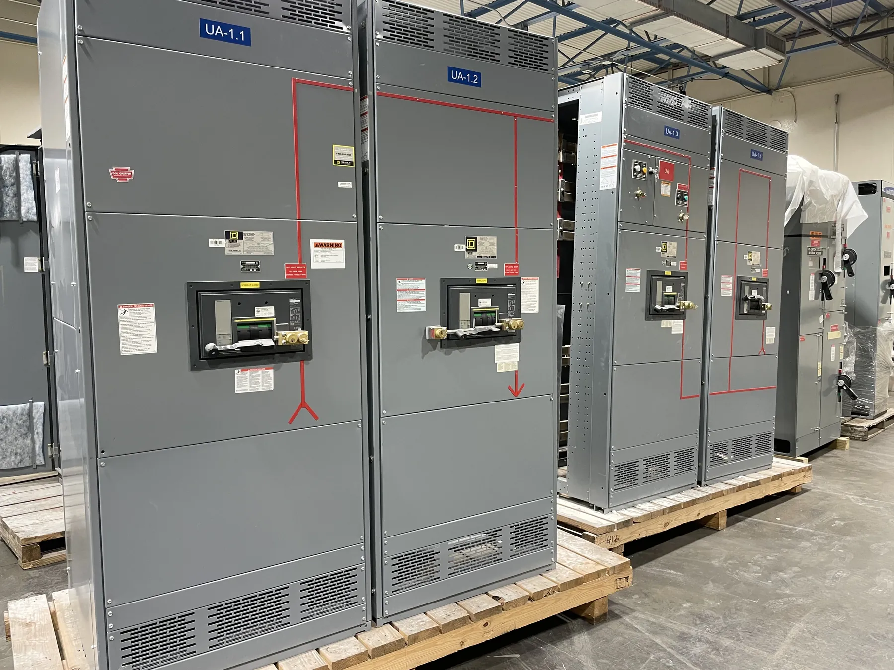
High-Voltage Substation Switchgear and Protective Relaying
High-voltage switchgear and its protective relays must be selected as parts of a coordinated substation design, not as isolated catalog items. The equipment must suit the system’s voltage class, insulation requirements, available fault conditions, switching duties, operating arrangement and utility interconnection criteria. A project’s nominal system voltage is not, by itself, a complete equipment rating. The responsible engineer must establish the applicable classifications and confirm that the proposed construction and ratings fit the installation.
Our U.S.-manufactured equipment is built with all-American components and can be shipped nationwide, including to Nevada. Exact available construction, ratings and documentation depend on the project requirements and must be confirmed for the proposed equipment. We manufacture new equipment for customer projects; we do not act as an equipment broker.
Voltage Classification, Insulation Levels and Construction
“High voltage” can describe different voltage classes in different project contexts. The specification should identify the system voltage and the required equipment classification, along with the insulation levels and other applicable nameplate ratings. These details affect the switchgear’s clearances, insulation system, switching devices, instrument transformers, terminations and physical arrangement. They cannot be inferred from a general product description.
Construction also depends on the substation’s function and layout. The engineer may need to define the number and arrangement of incoming, outgoing or transformer circuits, the required switching and isolation functions, bus configuration, enclosure or installation conditions, and interfaces with adjacent equipment. Confirming the exact available construction against the equipment documentation is essential before treating any configuration as suitable.
Protective Relaying Requirements and System Coordination
Protective relays detect specified electrical conditions and initiate actions through the project’s control and trip circuits. Their settings and logic depend on the power-system study, equipment characteristics, operating modes and protection philosophy. The relay package must be considered alongside the switching devices, current and voltage sensing, trip circuits, auxiliary power, communications and any required status or alarm signals.
Protection coordination is a system-level engineering task. Relay functions, settings, time delays and trip assignments should be reviewed against upstream and downstream devices, transformer protection, grounding arrangements and utility requirements. A relay selection or preliminary equipment configuration does not establish final settings or demonstrate coordination. The responsible protection engineer must review the project drawings, studies and equipment documentation, then resolve the design with the utility where required.
Utility Interconnection and Applicable Standards — High-Voltage Switchgear and Protective Relaying
Interconnection requirements can influence the switchgear lineup, metering and sensing interfaces, relay functions, communications, control power, trip paths and required documentation. Utilities may have project-specific criteria for protection, isolation, access, testing records or design review. Those criteria should be identified early and checked against the proposed configuration rather than assumed to be uniform across Nevada or across all service territories.
Applicable IEEE or IEC requirements depend on the equipment type, voltage class, project specification and governing design basis. The project team should identify the standards and editions that apply, and confirm the manufacturer’s offered construction and documentation against those requirements. No single standard statement should be taken to establish suitability for every high-voltage switchgear application or utility interconnection.
Information Needed for a Project Review
A useful quotation review starts with engineering inputs rather than a voltage figure alone. Provide the one-line diagram, equipment schedule, project specification, site and installation conditions, utility criteria, and available system-study information. Identify required circuit functions, bus arrangement, sensing and protection interfaces, control-power expectations, communications, and any specified standards or submittal documents. If the design is still developing, note open items so they can be clearly distinguished from confirmed requirements.
These inputs help establish what construction may be available and which details need engineering resolution. They also reduce the risk of comparing proposals that use different assumptions about ratings, protection scope or interconnection interfaces. Final ratings, listings where applicable, and project-specific features require confirmation in the equipment documentation and review by the responsible engineer.
Documentation, Nevada Logistics and Final Confirmation
For Nevada installations, shipping is only one part of project planning. Consider the delivery route and receiving access, unloading arrangements, site storage conditions, installation sequence and coordination with other substation work. These facility conditions can affect packaging, shipment planning and the timing of engineering submittals, but they do not determine the electrical design or establish an arrival date.
Before equipment is released for project use, the responsible engineer and utility should review the drawings, ratings, relay requirements and applicable documentation against the approved design. Confirm the actual available configuration and ratings from the equipment documentation. This project-specific review is the basis for resolving interfaces and requirements; a general product description cannot replace engineering approval or site review.