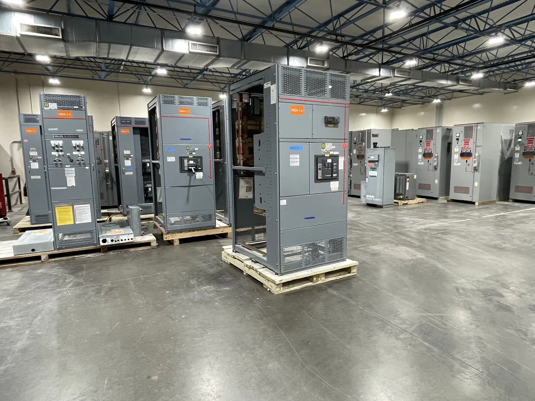
Electrical Busway for a 277/480 V Distribution System
Busway can distribute power through a building where a defined route and multiple connection points make a bus duct system a practical alternative to long runs of cable and conduit. For a 277/480 V application, the equipment must be selected for the actual system configuration, load, installation environment and available fault current—not voltage wording alone. A 480 V line-to-line system commonly serves three-phase equipment, while 277 V line-to-neutral service may supply compatible lighting loads in a four-wire arrangement. Confirm the source grounding, phase and neutral configuration, and intended loads with the project engineer before specifying the busway.
Our U.S.-manufactured electrical busway is built to order using all-American components and can ship nationwide, including to Nevada. Available configurations, ratings and lead times depend on the project requirements and must be confirmed against the equipment documentation. Provide the design information early so the proposed busway, fittings and connections can be reviewed as a coordinated system rather than as isolated parts.
Feeder and Plug-In Busway Serve Different Distribution Needs
Feeder busway carries power between distribution equipment or along a route where loads connect at designated points. It is generally selected around the source, destination, load profile and route. Plug-in busway includes provisions for compatible tap-off units at specified locations, which can support distributed loads where the system is designed for those connections. A plug-in section is not interchangeable with feeder busway by assumption: the busway type, tap units, orientation, enclosure and permitted use must match the manufacturer’s documentation.
Consider where equipment will be installed and how the distribution may need to change over time. A route serving fixed switchboards may favor a feeder arrangement, while a planned series of machine or lighting connections may call for plug-in sections. The design must account for the position and rating of every connection, access for maintenance, and any restrictions on tap-off use. Confirm how the busway interfaces with the source switchboard, downstream overcurrent devices and connected equipment.
Conductor Capacity, Neutral Sizing and Load Mix
Busway ampacity is a rating, not a substitute for calculating the system load. Selection depends on the expected demand, load diversity, continuous-load treatment where applicable, ambient and installation conditions, conductor material and the complete system configuration. The specified 277/480 V describes a voltage application; it does not establish the busway’s current rating, short-circuit capability or suitability for a particular load.
For a four-wire system supplying both 480 V line-to-line loads and 277 V line-to-neutral loads, identify the expected phase distribution and neutral current. Lighting drivers and other electronic loads can affect neutral loading, so do not assume that the neutral may be reduced or omitted. Neutral size and arrangement must follow the load analysis and equipment design. Motor feeders also require coordination with motor starting characteristics, branch protection and any local disconnecting equipment. The engineer should review the connected-load schedule, anticipated growth and applicable project requirements before finalizing conductor capacity.
Enclosure Conditions, Supports and Route Planning — Electrical Busway for 277/480 V
Busway enclosure selection depends on where the run will be installed and what conditions it will encounter. Indoor dry locations, areas exposed to dust or moisture, outdoor routes and spaces with unusual temperatures or corrosive influences can require different enclosure provisions. State the installation environment rather than choosing an enclosure from voltage alone. Confirm the documented environmental suitability for the exact busway and fittings being quoted.
Route planning should identify elevations, changes in direction, penetrations, transitions and available support points. Support spacing and attachment details must follow the applicable busway instructions and the building structure’s design; do not infer support requirements from another manufacturer’s system. Account for access to joints and plug-in openings, room for connected equipment, and any movement or clearance constraints. Nevada destinations can involve varied facility layouts and environmental conditions, so provide the actual indoor or outdoor location and relevant exposure details rather than relying on a regional assumption.
Connections and Listed-System Compatibility
Electrical continuity and mechanical fit depend on using compatible busway sections, joint packs, elbows, tees, end closures, tap-off units and transition pieces. Components from different systems should not be presumed compatible because they appear similar or carry comparable nominal ratings. The complete assembly must be specified as a matched system, with connector types, phase sequence, neutral and grounding arrangements, and connection orientation confirmed in the documentation.
Where a listed system is required, verify the listing and its scope for the exact product configuration, accessories and intended application. UL 891 applies to applicable low-voltage switchboards; it should not be treated as a blanket standard for busway. Busway listing information and any project-required approvals must be confirmed for the offered system. Equipment ratings, listings and compatibility require review against the project documents and the manufacturer’s published information.
Information Needed to Specify 277/480 V Busway
For a useful quotation review, provide the one-line diagram, source and load equipment details, phase and wire configuration, calculated load or required ampacity, available fault-current information, route drawings and installation environment. Include the proposed feeder or plug-in arrangement, connection locations, transition requirements, support constraints and any specified listing or enclosure conditions. Identify whether the system serves 480 V motors, 277 V lighting, mixed loads or another defined combination.
A qualified electrical engineer must verify the design, protection coordination, grounding and suitability for the site. Final ratings and the available configuration should be checked against the equipment documentation before release. With those inputs, the busway can be evaluated as part of the complete 277/480 V distribution system, including its interfaces with switchboards, protective devices and downstream loads.