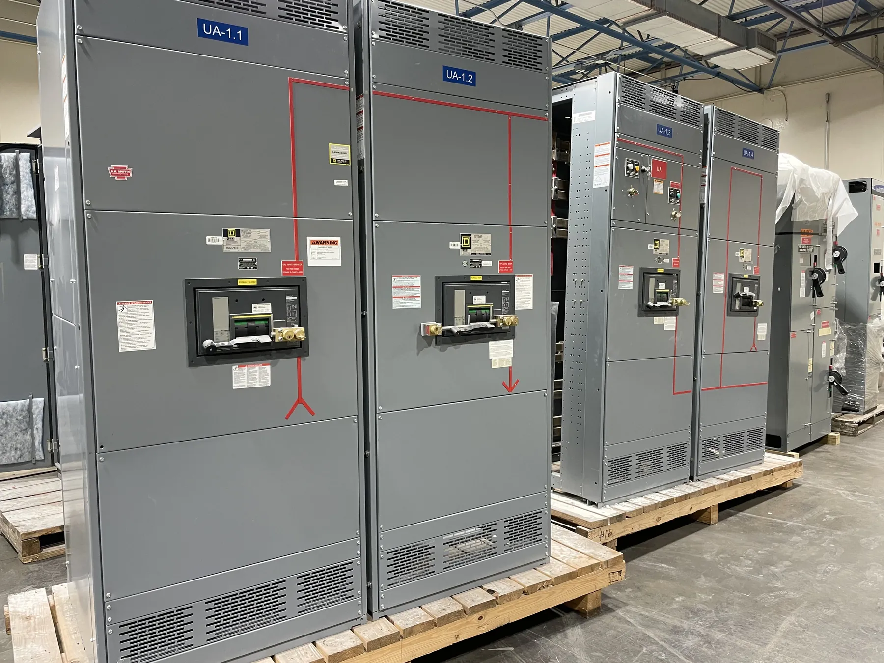
Electrical Busway for 120/208 V: Fit the System, Not Just the Label
Electrical busway for a 120/208 V system can distribute power through a building while providing designated points for downstream connections. The voltage description alone does not establish that a particular busway section or plug-in unit is suitable. Confirm the system configuration, equipment ratings, available fault current, installation conditions and compatibility of every connected component with the project documents and the proposed busway system.
For a new installation or expansion, begin with the electrical design and the equipment schedule. Identify whether the source is a three-phase, four-wire system, whether a neutral is required throughout the run, and which loads will connect at each point. A system’s nominal voltage is not the same as a busway’s current rating or short-circuit rating. Those values, along with listing information and permitted configurations, need to be verified for the actual product and application.
Feeder Busway and Plug-In Busway Serve Different Roles
Feeder busway carries power between electrical equipment or along a distribution route. It may be selected where the design calls for a defined path from a source to downstream distribution equipment. Plug-in busway can provide connection points along the route for compatible plug-in units, which may suit layouts where loads are distributed at multiple locations or where connection positions are part of the planned system.
These approaches are not interchangeable in every application. A feeder section may not provide the access points, enclosure features or connection arrangements needed for distributed loads. Plug-in sections require compatible units and must be installed in locations and orientations allowed by the manufacturer’s documentation. The design should account for the intended load locations, access for future work, circuit protection and the complete route—not simply the convenience of adding a tap later.
Conductor Capacity, Phase Configuration and Neutral Needs
Conductor capacity must be selected from the applicable product ratings and the engineered load assessment. The design team should consider the connected loads, demand assumptions, load balance among phases, expected growth and the effects of the installation environment. A stated 120/208 V service does not determine the required ampacity, and choosing a larger bus rating by itself does not resolve coordination or system-design questions.
Confirm the phase arrangement and neutral requirements for the actual loads. Some equipment may use line-to-neutral power, while other loads use line-to-line power. If neutral conductors are needed, their configuration and rating must be appropriate to the expected load characteristics and the busway system. Do not infer conductor sizing or neutral suitability from a general voltage label; verify details against the equipment documentation and qualified electrical design.
Enclosure Conditions, Supports and Route Planning — Electrical Busway for 120/208 V
Busway selection must match the physical environment and the route. Review exposure to moisture, dust, temperature, corrosion, mechanical impact and other conditions that may affect enclosure selection or installation. Indoor and outdoor conditions are not equivalent, and an enclosure designation should be confirmed for the exact section and application rather than assumed from the product category.
Support locations and methods are part of the installation design. The route plan should identify structural attachment points, section orientation, clearances, access for inspection and connection work, and any transitions around building features. Supports must be appropriate to the busway manufacturer’s instructions and site structure. Nevada facilities may also have varied building layouts and environmental conditions; shipping to a Nevada site does not replace a review of its actual installation conditions.
Connections, Fault Current and Listed-System Compatibility
Specify the source connection, end connections, elbows, offsets, expansion provisions and any other route components required by the layout. Interfaces must match the selected busway family and the connected equipment. Mixing sections or plug-in units from different systems should not be presumed acceptable. Confirm compatibility through the applicable product documentation, including the permitted components and connection arrangements.
Available fault current at the busway location is a key design input. The busway’s short-circuit rating and the protective-device coordination must be evaluated against the system conditions by qualified electrical professionals. Do not assume that a current rating establishes fault-current capability. Listings and standards apply only to the products and configurations they cover; confirm the exact listing, rating and scope for each proposed assembly. UL 891 applies to applicable low-voltage switchboards, not automatically to busway or every distribution product.
What to Provide for a 120/208 V Busway Quote
For a useful quotation, provide the one-line diagram or available system description, phase and neutral requirements, source and load information, required bus rating, available fault current, route drawings, environmental conditions, connection points and any specified listing or project requirements. Include dimensions and interface details for equipment at each end, plus the intended feeder or plug-in arrangement. Missing details can affect configuration and should be resolved before treating a proposed selection as final.
We manufacture new custom electrical busway and power-distribution equipment in the United States using all-American components, with short lead times supported by the business and nationwide shipping. The actual configuration, ratings, listing status and schedule depend on the project and must be confirmed in the equipment documentation and quotation. Final selection and installation details require review by qualified engineers and the project team.