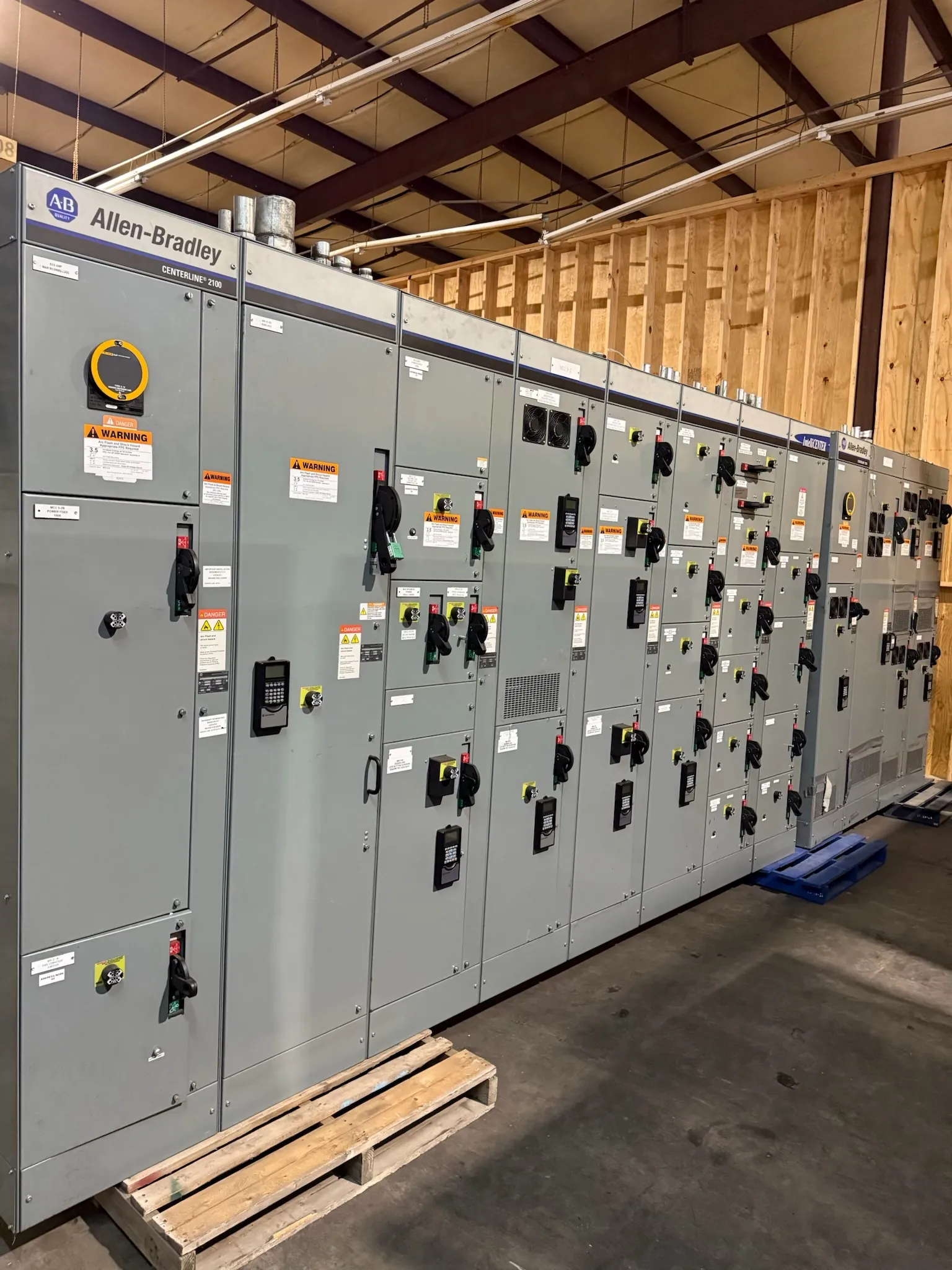
Design the Bus for the Assembly
Busbars distribute power between the incoming source and outgoing devices, but their size and shape cannot be chosen from current alone. For new equipment serving a Nevada project, the starting point is the approved one-line diagram, system voltage, phase arrangement, neutral and ground requirements, and the intended continuous current of each bus section. Device locations and cable or busway connections establish the paths the conductors must follow.
A U.S. manufacturer can use those inputs to prepare bus layouts that fit the complete assembly rather than a collection of isolated parts. The equipment designer and project engineer should review the specified ambient conditions, operating modes and future feeder allowances before dimensions and materials are released for fabrication.
Choose Conductors for Current and Conditions
Copper and aluminum are both used for power-distribution bus, but their properties, joint treatments and space requirements differ. The choice affects conductor dimensions, support spacing, connection hardware and temperature behavior. Neutral sizing depends on the actual system and load characteristics, while the equipment grounding bus follows its own design and code requirements. A bus material substitution is therefore an engineering decision, not merely a change in material preference.
Required current capacity must be supported by the assembly design and applicable test or engineering documentation. Enclosure ventilation, ambient temperature, conductor arrangement and proximity to heat-producing devices all influence performance. If all-American components are specified, define the required origin and evidence for conductors, hardware and other parts; U.S. assembly alone does not establish every component's origin.
Provide Mechanical Strength for Fault Duty
A short circuit produces forces between conductors as well as heating. The design must account for the available fault current and the equipment's applicable short-circuit withstand or short-circuit current rating. Braces, insulators, fasteners and their spacing are integral to that design. Changing a bus run or support position can affect the assembly's demonstrated capability even when the conductor cross section stays the same.
The project engineer should establish fault duty at the installation point, considering sources and operating configurations. The manufacturer then confirms that the proposed construction and protective-device arrangement are supported for that duty. A breaker interrupting rating and a bus withstand rating describe different capabilities; one does not automatically establish the other.
Fabricate and Join Conductors Precisely
Fabrication may include cutting, bending, punching and preparing contact surfaces to match the approved drawings. Dimensions must accommodate phase spacing, barriers and the physical interfaces to devices. Bend geometry, hole alignment and edge preparation matter because a forced connection can place stress on terminals or make the intended hardware arrangement impossible. Tolerances and surface treatments should be defined for the actual materials and design.
Bolted joints require the specified contact preparation, hardware and tightening procedure. Plating or a joint compound may be appropriate where the design calls for it, particularly at dissimilar-metal connections. Installation instructions should identify any field-made shipping-split joints, including the required assembly method, rather than leaving the connection details to assumption.
Coordinate Insulation, Barriers and Access
Insulation and barriers help achieve the clearances and isolation required by the selected equipment design. Their placement must work around bends, tap-offs, joints and removable devices without obstructing necessary access. The applicable product standard and design documentation determine the construction details; adding insulating material does not by itself validate an otherwise unsuitable layout.
Grounding continuity, safe access for maintenance and cable termination space also belong in the bus layout review. For a Nevada site, the project should identify actual indoor or outdoor exposure, dust and ambient temperature rather than assuming a single statewide environment. The qualified design team must evaluate the resulting enclosure and maintenance provisions.
Verify Fabrication and Plan the Handoff
Before release, agree on drawing review, dimensional checks, material identification and inspection of joint preparation, supports and barriers. The manufacturer should document the checks and any required electrical tests under the project plan. Request the applicable assembly ratings and supporting documentation rather than treating a conductor size as proof of a complete equipment rating.
Shipping dimensions and split points should be coordinated with the Nevada receiving route and the installer's handling capacity. Final documentation can identify bus splice locations, hardware, tightening instructions and any field verification needed after sections are joined. Qualified personnel remain responsible for installation, required inspections and energization.