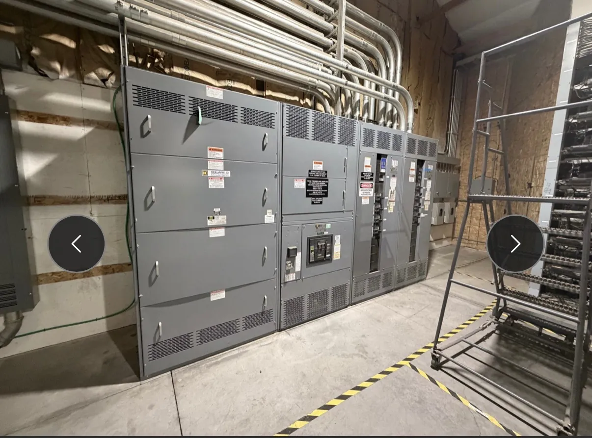
Metal-Clad Switchgear for Winnemucca, NV Projects
Metal-clad switchgear can be a fit for medium-voltage distribution projects where the design calls for separated compartments and withdrawable circuit breakers. For a Winnemucca facility, the equipment should be specified around the actual power system, connected loads, operating plan and site conditions—not selected by location or product name alone. We manufacture new custom power-distribution equipment in the United States using all-American components, and ship nationwide, including to Nevada. Project requirements determine the configuration and ratings; engineering review is needed before they are finalized.
Compartmentalization and Internal Arrangement
Metal-clad construction uses grounded metal barriers to separate major functional sections, such as the main bus, circuit breaker and cable terminations. This compartmentalization affects how equipment is arranged, accessed and maintained, but it does not eliminate electrical hazards or replace a project-specific safety assessment. The proposed lineup must match the one-line diagram and account for incoming sources, feeder count, bus arrangement, metering, control power and any required auxiliary sections.
Compartment dimensions and access provisions also influence cable entry, termination space and the position of adjacent equipment. Confirm whether conductors enter from above or below, how they approach the lineup, and whether the room provides the clearances and access required by the final design. Where future expansion is anticipated, identify it early: reserved lineup space, spare provisions and bus or control arrangements may affect the initial configuration.
Withdrawable Breakers, Ratings and Interfaces
Withdrawable breakers are installed in a defined cell and can be moved between specified positions as part of the equipment design. Their arrangement can support maintenance and replacement planning, but the breaker, cell, bus and control interfaces must be compatible as a coordinated assembly. Breaker type, interrupting capability, continuous-current rating, control voltage, auxiliary contacts and trip functions are among the details that need confirmation.
Do not treat a voltage rating as the system voltage, or assume that a nominal system description establishes every equipment rating. The project team should provide system voltage, frequency, available fault current, grounding method and relevant operating conditions. Engineers can use these inputs to evaluate equipment ratings and configuration. Any listing or standard claim must likewise be confirmed for the specific product and scope rather than inferred from the term “metal-clad.”
Grounding and Relay Coordination — Metal-Clad Switchgear in Winnemucca, NV
Grounding choices affect fault behavior, protection settings and the equipment’s relationship to the broader distribution system. Project documents should identify the grounding method and relevant source and transformer arrangements. The switchgear grounding bus, cable grounding provisions, instrument transformers and protection scheme must be reviewed together; a grounding detail cannot be settled from the switchgear description alone.
Relay coordination requires system data, protective-device information and the owner’s operating objectives. Provide the one-line diagram, available fault-current study or other established fault data, upstream and downstream device details, transformer information, and intended trip and alarm functions. A qualified engineer should review settings and time-current coordination against the complete system. Changes to breakers, relays, transformers or utility conditions can affect that review, so coordination assumptions should be documented and revisited when the design changes.
IEEE C37.20.2 Scope and Project Confirmation
IEEE C37.20.2 addresses metal-clad switchgear. Its applicability and the required edition or project-specific provisions should be stated in the procurement documents and confirmed against the proposed assembly. The standard is not a substitute for defining system voltage, ratings, environmental conditions, protection requirements or interfaces. Nor should its mention be taken as proof that a particular assembly is listed, certified or compliant; those claims require confirmation for the actual product and project scope.
For a useful quotation, provide the one-line diagram, equipment schedule, ratings and fault-duty basis, breaker and relay requirements, cable entry and termination details, control schematics where available, and applicable project specifications. Identify required documentation, inspection or testing expectations, and any owner or engineer review points. These inputs help distinguish firm requirements from open design questions before the lineup is configured.
Winnemucca Receiving, Unloading and Installation Planning — Metal-Clad Switchgear in Winnemucca, NV
Coordinate shipment planning with the final installation schedule. A lineup may ship as multiple sections, and allowable section dimensions, weights, handling points and shipping splits depend on the approved design. Confirm the receiving location’s access route, overhead and doorway constraints, turning space, unloading equipment and capacity, staging area, and path from unloading point to the electrical room. Site personnel and the project’s qualified logistics team should verify handling plans against the actual shipping documents and site conditions.
Align delivery windows with room readiness, foundation or floor provisions, cable work and installation resources. If the site cannot receive the complete lineup at once, discuss feasible shipping and staging arrangements during design rather than assuming sections can be divided or stored without consequence. Final installation and electrical design decisions belong with qualified project engineers and site reviewers. We can use the confirmed requirements to develop a new custom equipment proposal and coordinate the manufacturing and shipment details for the Winnemucca project.