Metal-Clad Switchgear Design for Sparks, Nevada Projects
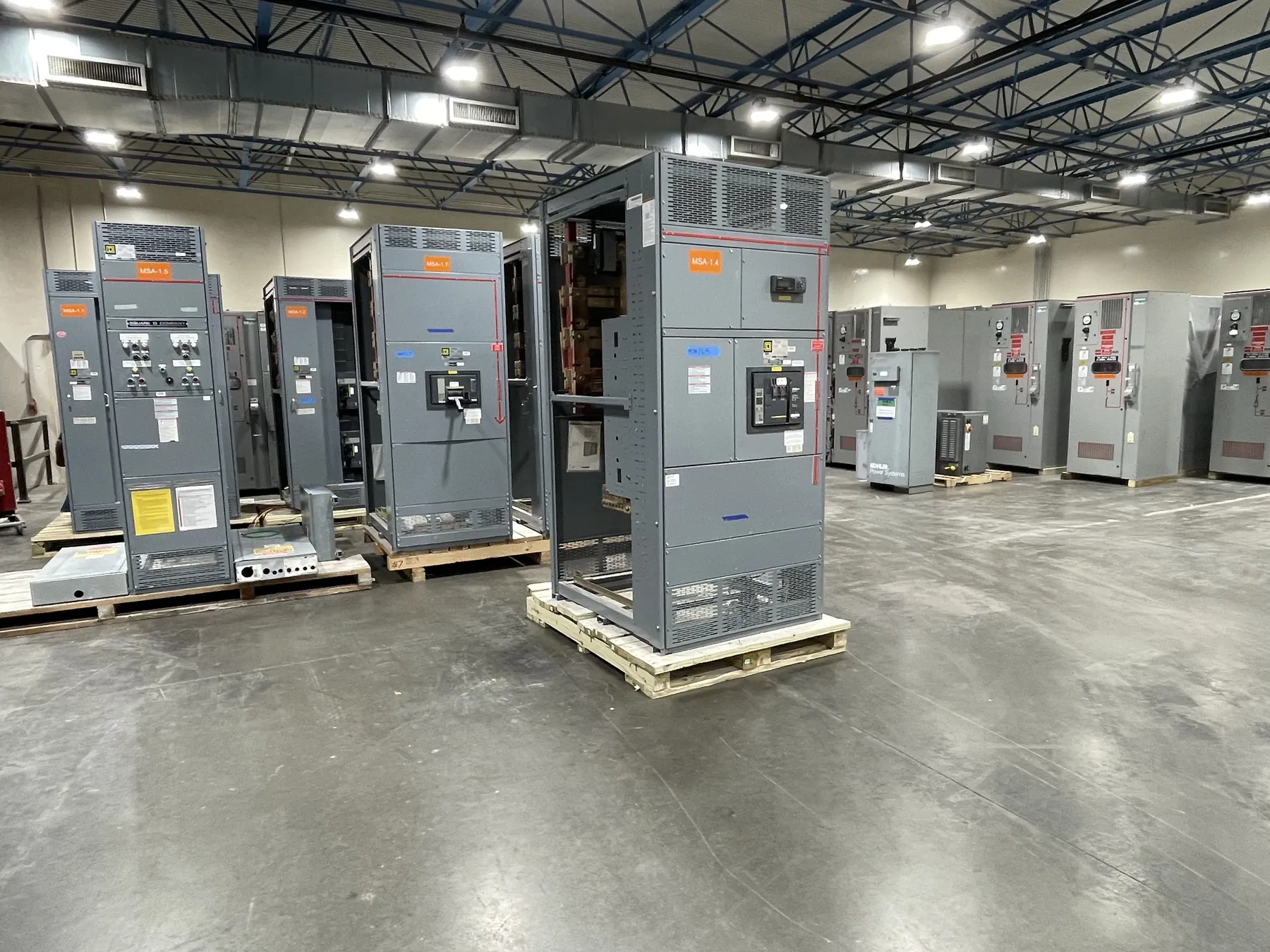
Metal-clad switchgear is a medium-voltage assembly designed to separate major components into grounded metal compartments. For a Sparks facility, the design should begin with the one-line diagram, the service arrangement and the operating needs of the site—not a catalog description alone. The proposed equipment must match the project’s system voltage, available fault current, load characteristics and connection details. A qualified electrical engineer should confirm the design against site conditions and applicable requirements before equipment ratings or configuration are selected.
We manufacture new custom switchgear in the United States using all-American components and ship nationwide, including to Sparks. Project schedules depend on confirmed design inputs, component selection and manufacturing requirements; a short lead time can be supported, but a specific schedule needs review. Nevada delivery planning should account for receiving access, unloading arrangements, indoor placement and the route from the delivery point to the electrical room. Those conditions can affect enclosure configuration, shipping sections and installation sequencing.
Compartmentalization and Withdrawable Breaker Choices — Metal-Clad Switchgear in Sparks, NV
Metal-clad construction uses grounded barriers to divide the assembly into compartments, commonly separating the bus, circuit breaker and cable connections. This arrangement can limit exposure between sections during inspection or maintenance, but compartmentalization does not by itself determine the equipment’s arc-flash performance or make energized work safe. The complete design, operating procedures and site-specific hazard assessment remain important.
Withdrawable breakers can be moved between connected, test and disconnected positions, subject to the equipment design. Their selection involves more than choosing a breaker frame: engineers must establish the required interrupting capability, continuous-current rating, control power, trip functions, interface dimensions and mechanical interlocks. The design should also address how breakers are handled and stored, whether future spare breakers are planned, and how controls and indications align with the facility’s operating requirements. These choices affect compartment dimensions, auxiliary wiring and maintenance planning.
Grounding, Cable Terminations and Site Interfaces
Grounding details must suit the switchgear arrangement and the facility’s grounding system. Design review should cover the ground bus, equipment bonding, incoming and outgoing cable connections, and any specified grounding provisions. Cable entry direction, termination space, conductor type and bending requirements can constrain section layout. Confirming these interfaces early helps avoid conflicts with conduits, trenches, adjacent equipment and room clearances.
For Sparks facilities, environmental and building conditions should be documented rather than assumed. Indoor or outdoor placement, ambient conditions, elevation, dust exposure, seismic criteria where applicable, ventilation and access restrictions may influence enclosure and installation details. The site team should verify room dimensions, door openings, equipment handling paths and the location of adjoining transformers or other gear. These details are useful quotation inputs because they shape both the physical assembly and its connection points.
Applicable IEEE C37.20.2 Requirements and Ratings
IEEE C37.20.2 is the relevant standard to evaluate for metal-clad switchgear. The project specification should identify the applicable edition and required construction, ratings and tests, then confirm that the proposed assembly is designed and documented to meet the project’s stated requirements. Applicability and compliance must be reviewed for the actual equipment and scope; a standard reference alone is not proof that a particular assembly is listed, certified or suitable for a given installation.
Voltage class, continuous-current rating and short-circuit ratings are distinct design considerations. A rating is not the same as the facility’s system voltage, and equipment suitability cannot be inferred from one value in isolation. The engineer must verify the system grounding, insulation requirements, fault duty, operating conditions and interfaces. Any required listing, documentation or project-specific acceptance criteria should be identified and confirmed before finalizing the quotation.
Fault Current and Protective-Device Coordination
For a Sparks project, obtain the available fault current at the actual connection point from the utility or other responsible source. The value and assumptions should be current for the proposed service configuration. The engineer then compares the available fault duty with the switchgear and breaker capabilities, accounting for the system arrangement and relevant operating scenarios. If the service, transformer or source configuration changes, the fault-current basis may change as well.
Protective-device coordination should include the switchgear relays and breakers alongside downstream protective devices and loads. Relay functions, current-transformer details, settings ranges and trip characteristics need to reflect the one-line diagram and the project’s protection objectives. Coordination is an engineering study, not a default setting provided by the equipment manufacturer. The study should consider selective isolation where required, equipment withstand limits, motor starting or other load behavior, and any upstream protection constraints. Final settings and protection decisions belong to qualified project engineers.
Information for a Switchgear Quotation
A useful request for quotation includes the one-line diagram, system voltage and grounding, available fault current at the connection point, load and feeder information, required ratings, relay and control preferences, cable entry details, and applicable IEEE C37.20.2 requirements. Include the project location in Sparks, indoor or outdoor conditions, room and access constraints, delivery expectations, and any specified documentation or acceptance criteria. With those inputs, the equipment configuration, interfaces and schedule can be reviewed against the actual project rather than assumed from a general product description.