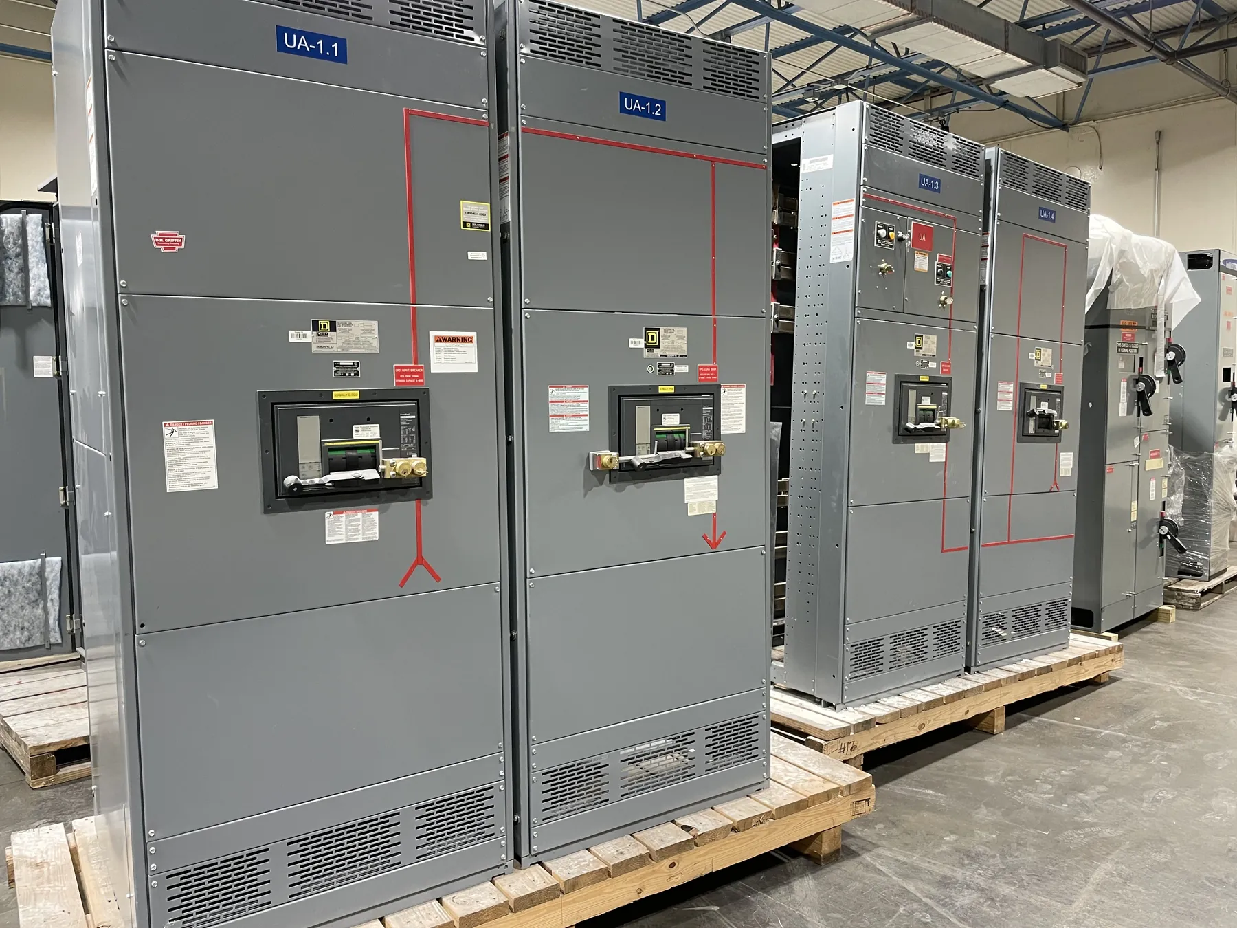
Medium-Voltage Switchgear for Sparks, Nevada Projects
Medium-voltage switchgear is selected to control, protect and isolate portions of an electrical distribution system at a voltage above the low-voltage range. For a Sparks facility, the right assembly depends on the utility or other source connection, the site distribution plan and the equipment that will receive power—not on the city name alone. Our U.S.-built, custom-manufactured assemblies use all-American components and are offered for projects shipping to Sparks and elsewhere nationwide. We manufacture new equipment for customer projects; final configuration and suitability must be established through project engineering and site review.
Start by defining the system’s nominal voltage and the equipment’s required voltage class. These terms are related but not interchangeable: the system voltage describes the network, while the switchgear class identifies the equipment’s applicable design range. The one-line diagram, source information and connection requirements help establish the intended application. A voltage class should not be inferred from a general description such as “medium voltage” or from the rating of connected equipment.
Fault Duty, Insulation and Equipment Selection
Available fault current at the proposed connection point is a central quotation and design input. Ask the serving utility or responsible electrical engineer for the applicable value and basis, including relevant source and transformer information. The switchgear’s short-circuit and withstand capabilities must be appropriate for the actual system conditions. A rating that appears adequate in isolation may not be suitable if the upstream source, transformer impedance, parallel sources or planned system changes alter fault duty.
Insulation level is another distinct selection. The required insulation coordination depends on system voltage, grounding, switching conditions, surge exposure and the project’s design criteria. It should be reviewed with the equipment configuration and protective scheme rather than treated as a generic accessory choice. The project team must also identify environmental and installation conditions that affect enclosure and component selection, such as indoor or outdoor placement, ambient conditions, available space and access for cable entry and maintenance.
Protective Relays and Downstream Coordination
Relay functions and settings should reflect the source, switchgear arrangement and downstream loads. The engineer responsible for the electrical system needs to coordinate protective devices from the point of connection through transformers, feeders and load equipment. That review considers fault levels, equipment capabilities, load characteristics and the intended protection philosophy. A relay model or a list of standard functions alone does not establish that the system is coordinated.
Useful quotation information includes the one-line diagram, source fault-current data, transformer details, feeder descriptions, load characteristics and any project protection requirements. Include known upstream and downstream device information where available. If those inputs are incomplete, identify what remains to be confirmed instead of treating an assumed value as final. Settings and coordination decisions require qualified engineering review; they cannot be determined from a switchgear description alone.
Cable Terminations, Interfaces and Physical Layout
Cable termination requirements shape both the equipment arrangement and the site interface. Specify cable type and size when established, termination approach, entry direction, phase arrangement and the location of incoming and outgoing circuits. Confirm whether the project requires provisions for particular connectors or termination components, and identify the equipment connected on each side of the lineup. These details influence compartment layout, clearances and installation planning.
Also provide available room dimensions, access routes, floor or support conditions, cable trench or conduit information and any restrictions on delivery or placement. Sparks facilities vary, so local weather exposure, dust, enclosure location and maintenance access should be described for the actual site rather than assumed. Shipping to Nevada can be planned as part of the project, but site unloading, movement into the building and final installation require coordination with the facility team and qualified contractors.
What to Provide for a Sparks Switchgear Quote
A complete request helps distinguish confirmed requirements from open design questions. Share the project voltage and grounding approach, available fault current at the connection point, required fault-duty and insulation criteria, one-line diagram, relay and coordination requirements, cable details, enclosure location and applicable interface documents. Note anticipated changes to the electrical system if they could affect ratings or protective-device coordination. These inputs support a more useful review without implying that an equipment selection can be finalized before engineering.
Project schedules should identify required submittals, review milestones, shipping destination and site constraints. Custom manufacturing can support short lead times, but a specific production or delivery date depends on the final scope, engineering information, approvals and project conditions. Confirm the proposed configuration, ratings, listings if applicable, and interface responsibilities during the technical review. UL 891 applies to applicable low-voltage switchboards; it should not be used to describe or substantiate medium-voltage switchgear.
Engineering Review Before Release
Before equipment is released for manufacture, the project team should reconcile the source data, protection requirements, cable interfaces, layout and site conditions. Changes to the utility connection, transformer, downstream loads or operating arrangement may affect the design and must be reviewed. The responsible engineers determine whether the proposed ratings and configuration fit the installation; the equipment manufacturer needs accurate project information to build to the approved scope. This coordinated approach helps a Sparks project move from a general medium-voltage requirement toward a clearly defined, manufacturable assembly.