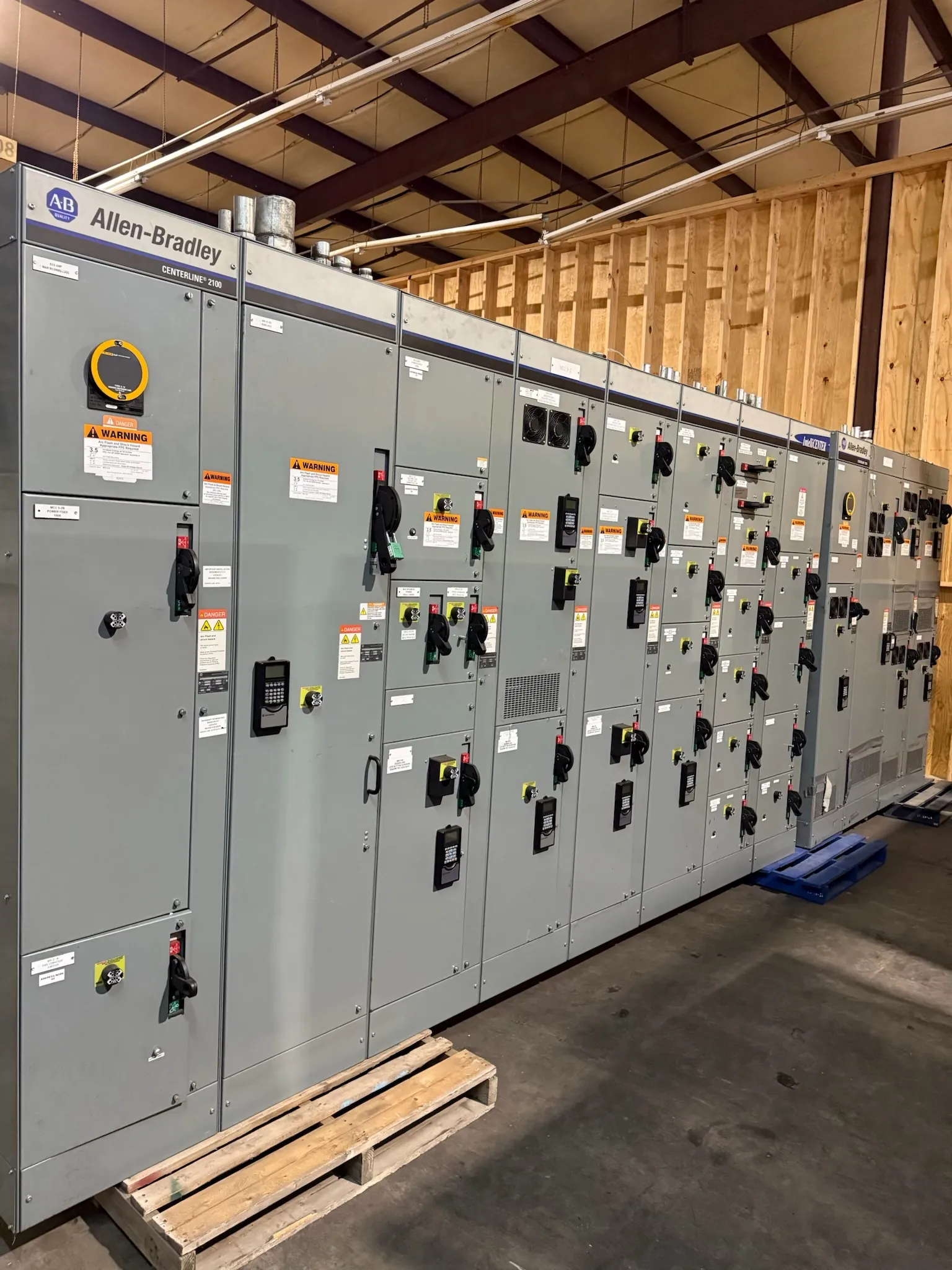
Manufacturing Switchgear for Sparks Production Facilities
Manufacturing electrical distribution in Sparks must account for how production actually runs: which loads operate together, which processes can pause, and what a shutdown means for people, product, and equipment. A custom switchboard or switchgear assembly should be developed around the facility’s electrical design and operating requirements, not selected by equipment name alone. Early coordination among the facility team, electrical engineer, contractor, and equipment manufacturer can clarify the scope before drawings and pricing are finalized.
Start by mapping the intended distribution from the service or transformer interface through the main device, distribution sections, and outgoing feeders. Identify production lines, process equipment, building services, and planned additions. A load list should distinguish normal operating loads from equipment that may start together or remain energized during a process interruption. Those operating details help the engineer assess demand, feeder arrangements, and protective-device coordination.
Translate Production Loads Into a Practical Lineup
Motor-driven machinery can make the distribution plan more involved than a simple count of circuits. The project team should identify motor ratings and starting methods, drive equipment, control power needs, and whether multiple motors start concurrently. Large or frequently started motors may affect voltage drop, protective-device selection, and coordination with upstream equipment. These questions require engineering review using the actual system information; they cannot be resolved from a general equipment description.
Motor controls may be part of the switchgear scope, supplied separately, or arranged in adjacent equipment. That boundary affects lineup dimensions, wiring interfaces, control diagrams, and responsibility for commissioning coordination. Confirm whether the package needs space or provisions for future controls, and document who furnishes field wiring, control devices, and interconnections. If variable-frequency drives or other power-electronic loads are involved, provide their electrical and operating details for review rather than assuming they fit a standard arrangement.
Set Ratings From the System, Not the City
Sparks is the project location, but it does not determine an assembly’s voltage, current rating, or interrupting capability. Those choices depend on the service, transformer, grounding arrangement, load, and available fault current at the connection point. Obtain the available fault-current information for the proposed connection and provide it to the responsible engineer and manufacturer. The engineer must evaluate the system and protective devices together, including relevant upstream and downstream equipment.
Also identify the intended installation environment and applicable project requirements. Indoor or outdoor placement, enclosure needs, ambient conditions, working space, cable entry, and access for maintenance can influence construction and layout. Equipment ratings, applicable standards, and any required listing must be confirmed for the specific assembly and application. UL 891 may apply to low-voltage switchboards where appropriate; it should not be treated as a blanket designation for all switchgear or other equipment types.
Coordinate Fault Current and Downstream Protection
Protective-device coordination is especially important where a manufacturing process has different priorities for different loads. The design team may need to consider which feeder should clear a fault, what equipment is downstream, and how an interruption could affect connected processes. Provide one-line diagrams, device information, load data, and available fault current so qualified engineers can evaluate the proposed arrangement. Device selections and settings require review against the actual system, governing requirements, and project objectives.
Do not assume that a rating on a device alone establishes suitability for the entire assembly or installation. Confirm the required assembly ratings, system conditions, and interfaces as a coordinated package. Changes to transformers, upstream protection, feeder lengths, or connected equipment can alter the engineering basis, so revisions should be communicated before final design and release.
Plan Future Feeder Space and Shutdown Constraints
Future capacity is more than leaving an empty space in a lineup. Discuss likely additions, their expected load characteristics, feeder destinations, and whether future work should be accommodated by reserved sections, provisions, or a later equipment expansion. The engineer can assess how those choices affect bus and device ratings, physical dimensions, and initial cost. Avoid specifying spare capacity as an unqualified percentage when the expected loads are not yet defined.
For a retrofit or facility expansion, develop a workable shutdown sequence with the site team and electrical contractor. Identify existing equipment that must remain in service, the intended cutover boundary, and any constraints on access, staging, or outage duration. A manufacturer can coordinate equipment interfaces and production details, but the site’s qualified electrical professionals must determine the installation and switching plan. No schedule should be assumed until scope, drawings, approvals, and site conditions are understood.
Prepare a Useful Sparks Project Quotation Package
A complete request helps align the quotation with the actual manufacturing application. Include the one-line diagram, equipment schedule, available fault current at the connection point, system voltage and grounding details, load and motor information, protective-device requirements, enclosure and installation conditions, and the desired future feeder provisions. Note the project stage, required submittals, delivery destination, and any known site access or receiving constraints. Shipping to Sparks can be coordinated as part of the project; it does not imply a local manufacturing facility or a predetermined delivery date.
The manufacturer can use those inputs to develop a proposed configuration, identify open technical questions, and coordinate drawings and interfaces with the project team. Assemblies are manufactured in the United States using all-American components and can ship nationwide. Lead times depend on the finalized scope and project requirements; confirm the schedule during quotation and order coordination. Before release, qualified engineers and the responsible project professionals should verify ratings, protective-device coordination, applicable standards, and installation details for the specific Sparks facility.