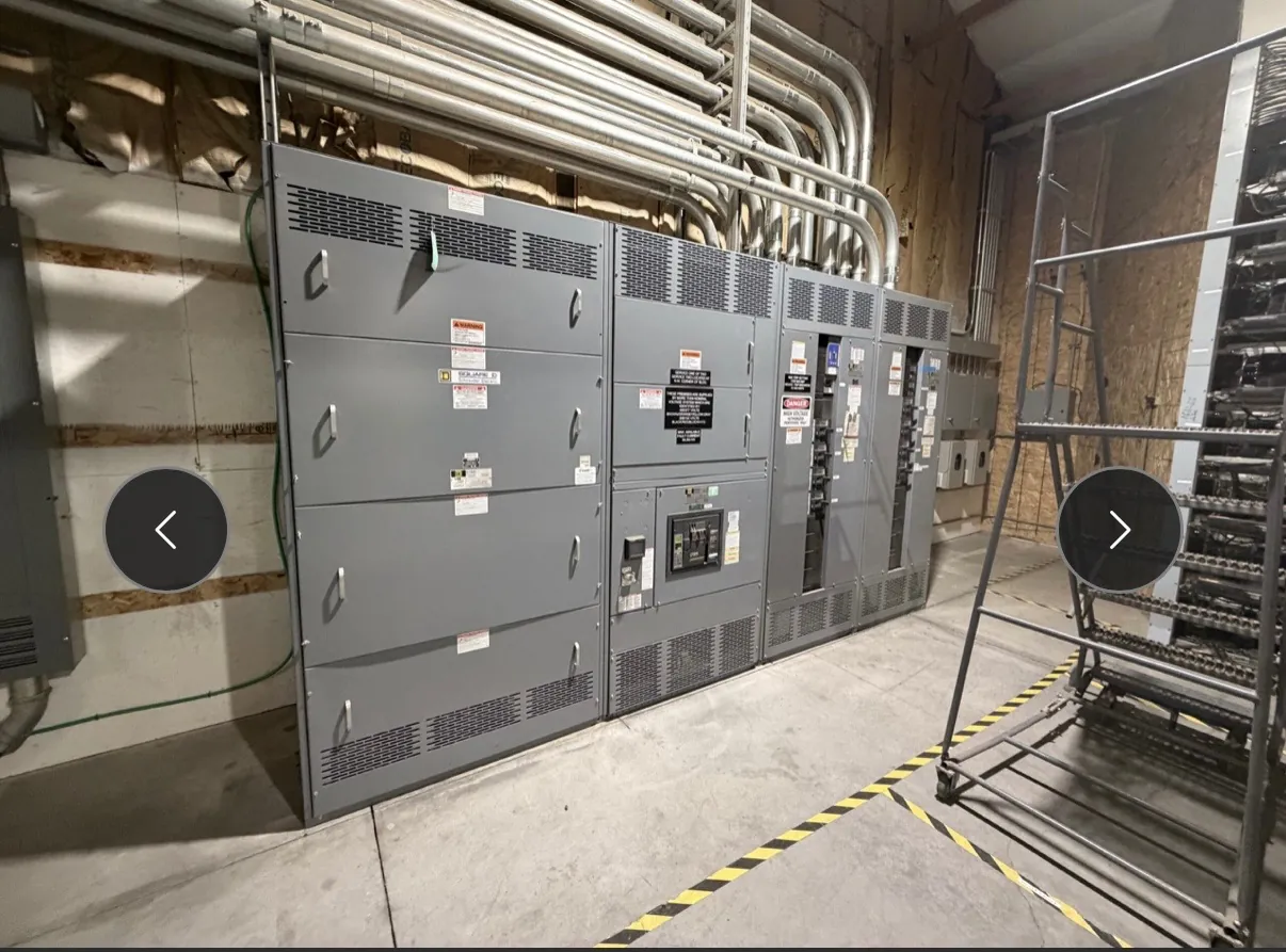
Pad-Mounted Switchgear for Lovelock, Nevada Projects
Pad-mounted switchgear can provide an outdoor point for switching and distributing power where a project’s layout calls for enclosed equipment near underground circuits. In Lovelock, the right configuration depends on the electrical design, the serving utility’s interface requirements, the site plan and the equipment’s intended role—not simply on choosing an enclosure that fits a pad. We manufacture new custom power-distribution equipment in the United States using all-American components. For Nevada projects, we can discuss a proposed configuration and ship equipment nationwide; project details and timing must be confirmed during quotation.
Enclosure Placement and Environmental Protection
Outdoor placement affects enclosure selection and the surrounding civil work. The design team should identify exposure to weather, dust, road spray, landscaping, vehicle traffic and other site conditions that could affect access or equipment protection. A pad-mounted enclosure also needs suitable working space and a location that does not conflict with drainage, fencing, adjacent equipment or planned maintenance access. Describe the actual site rather than assuming a standard enclosure or finish will suit every Lovelock installation.
Environmental protection is a coordinated design choice. Enclosure construction, openings, barriers and finish requirements should be reviewed against the specified application and the manufacturer’s available design. If the equipment will be near a road, loading area or public-facing space, note the risk of impact and any physical protection planned by the project. Final enclosure details should be confirmed with the project engineer and applicable utility requirements.
Foundation, Cable Entry and Site Interfaces
The foundation is part of the equipment interface, not an afterthought. Confirm the required pad dimensions, mounting arrangement, cable opening locations and clearances from the approved equipment drawings before concrete work proceeds. The civil and electrical teams should coordinate conduit routing, stub-up locations, bend space and cable pulling paths. A mismatch between the pad openings and the switchgear layout can complicate installation, so the equipment configuration and foundation design need to advance together.
Specify whether conductors enter from below and identify the intended direction and arrangement of incoming and outgoing circuits. Cable type, termination approach and available space can influence compartment layout and equipment dimensions. Where existing duct banks or site constraints limit routing, share those conditions early. Final cable and termination compatibility requires engineering review; it should not be inferred from a general product description.
Feeder Quantity, Switching Arrangement and Ratings
Feeder count is a key quotation input because the required number of ways and their functions shape the switching arrangement. Identify each incoming source, outgoing feeder and any planned tie or sectionalizing function. Note whether the equipment serves a new installation or must interface with existing distribution, and provide the available one-line diagram when possible. The project team should also clarify normal operating configuration and any requirements for future expansion.
Equipment ratings must be selected for the specific electrical system and duty. A rating is not the same as system voltage, and a product’s stated rating alone does not establish suitability for a particular installation. Provide the system information, fault-duty requirements and other design criteria established by the qualified engineer. Applicable listings and standards depend on the equipment type and configuration; confirm what applies to the proposed assembly rather than assuming a listing covers every switchgear product.
Utility Interface and Commissioning Responsibilities
Utility interface details should be settled before the configuration is finalized. Confirm the serving utility’s requirements for connection points, compartment arrangement, access, identification and any review or approval process relevant to the project. Utility criteria can differ, so do not rely on assumptions drawn from another site or service area. The engineer, owner and utility should align on the interface information used for design and procurement.
Set commissioning responsibilities early as well. Clarify who will coordinate installation checks, field connections, required inspections, testing and energization planning. These activities depend on the approved design, site conditions and responsible qualified personnel. The manufacturer can build to confirmed project requirements, but commissioning scope and acceptance criteria should be assigned by the project stakeholders.
Information for a Lovelock Equipment Quotation
A useful quotation package includes the one-line diagram, requested feeder quantities and functions, system and equipment rating requirements, cable-entry plan, foundation constraints, environmental conditions and utility interface criteria. Include delivery access information as well: site location, unloading arrangements, route restrictions and who will receive and handle the equipment. Lovelock’s site logistics can vary by facility, so describe actual access and staging conditions rather than relying on a general assumption about the area.
Early coordination helps align the manufactured assembly with civil work, cable routing and project responsibilities. We can review the information provided, identify open configuration questions and confirm applicable ratings, listings, lead time and shipping details for the specific order. Those items require project-specific confirmation before they are treated as final.