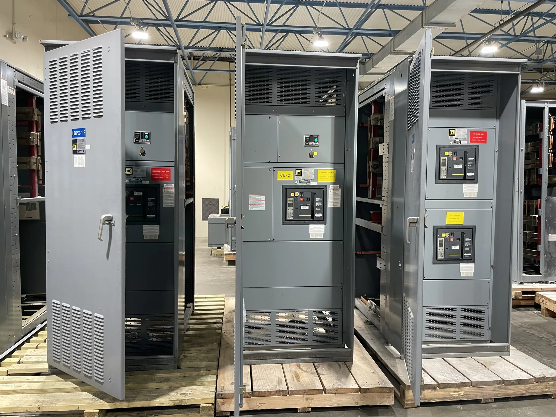
Motor Control Centers for Lovelock, Nevada Projects
Motor control centers (MCCs) bring motor starters, control components and associated distribution equipment together in a coordinated assembly. For a Lovelock facility, the right arrangement depends on the motors and driven loads, the electrical supply, operating sequences and the space available for installation and service. A custom MCC should be developed from project requirements rather than selected by enclosure appearance or a general product description alone. Our U.S.-built assemblies use all-American components, and we ship nationwide, including to Nevada. Final configuration, ratings and delivery arrangements are confirmed for each project.
Start with an equipment schedule that identifies each motor, its load, operating method and control interface. Note which motors require across-the-line starting, reduced-voltage starting or variable-frequency drives (VFDs), and identify any loads that need bypass operation or a particular control mode. Those choices affect starter construction, heat management, wiring, protection and the amount of space required within the lineup.
Starter and VFD Choices Shape the MCC Layout
Motor starters are selected and coordinated with the motor and the branch-circuit protection, not simply matched to a horsepower value. The project team should provide motor nameplate information, supply characteristics and the intended starting frequency and duty. Starting current, acceleration requirements and the driven equipment’s response can influence whether a conventional starter or VFD is appropriate. A VFD can support speed control and process integration, but it also introduces equipment-specific considerations such as heat dissipation, cable requirements and potential effects on the electrical system.
For VFD sections, identify who supplies the drive, who configures its control interface and how commands, status and fault signals are exchanged with the plant control system. Confirm whether the design calls for a disconnecting means, bypass arrangement, line-side components or other accessories, and assign responsibility for those items. Not every application needs the same features. Coordination among the MCC manufacturer, controls contractor, motor supplier and project engineer helps prevent gaps between the equipment schedule and the actual control sequence.
Short-Circuit Ratings and Feeder Protection Need System Context
An MCC’s short-circuit rating must be evaluated against the available fault current and the protective devices and system conditions at the installation point. It is not interchangeable with nominal system voltage, and a higher rating should not be assumed to resolve every coordination issue. The responsible electrical engineer should establish the applicable system data and protection approach, including the upstream device and any required coordination with downstream motor branch circuits.
Feeder quantities and feeder details also shape the lineup. For each incoming or outgoing feeder, provide the intended function, electrical characteristics, protective-device requirements, conductor arrangement and destination. Confirm whether a feeder serves a motor, a distribution panel or another load, since those applications can call for different equipment and coordination. Ratings, device selections and any listing requirements must be reviewed against the complete design and project documentation; they should not be inferred from a general MCC description.
Confirm Whether UL 845 Applies to the Specified Assembly
Ask the project engineer or specifying authority whether UL 845 is required for the motor control center and how that requirement is stated in the project documents. The applicable standard, listing scope and construction requirements depend on the specified equipment and configuration. UL 845 should not be treated as a blanket claim for equipment that has not been confirmed for the particular design. Include any required listing, documentation or inspection expectations in the RFQ so they can be reviewed before the assembly is quoted.
Alongside the standard question, document system voltage, frequency, bus arrangement, enclosure requirements and environmental conditions. Lovelock site conditions may differ between indoor electrical rooms and exposed or process-area locations. Temperature, dust, moisture, corrosive exposure, ventilation and available working space can affect enclosure and layout decisions. Site review and qualified engineering input are important where those conditions influence equipment suitability.
Plan Access, Installation and Nevada Delivery Early
Maintenance access is a design input, not an afterthought. Provide room dimensions, door and aisle constraints, cable entry preferences, ceiling or overhead obstructions, and the location of nearby piping or equipment. The project team should consider how technicians will reach devices and wiring compartments for inspection and service, while preserving the clearances and access required by the approved design and applicable codes. A lineup that fits a drawing may still present installation or service challenges if access routes and field connections are not coordinated.
For delivery to Lovelock, establish the receiving location, unloading capability, access route and any restrictions on delivery hours or staging. Confirm who is responsible for moving the equipment from the receiving point to its final location and for coordinating rigging or installation. These details can affect shipping configuration and packaging decisions. Delivery handling should be agreed upon before release rather than left to assumptions about site equipment or access.
Build the Quote Around Feeder Schedule and Responsibilities
A useful quotation package includes the one-line diagram, motor and feeder schedules, control schematics or sequence descriptions, available fault-current information, required ratings, enclosure and environmental details, and any applicable UL 845 language. Identify required spare spaces or future sections and distinguish them from fully equipped feeders. Also state the preferred incoming and outgoing cable arrangements, control-system interfaces and documentation expectations.
Set commissioning responsibilities early. Clarify who performs field wiring, verifies control signals, configures drives, checks protection settings and coordinates startup with connected equipment. The manufacturer can build to an approved project design, but final engineering decisions and site-specific commissioning require the responsible qualified professionals. Clear division of work—along with confirmed feeder quantities and delivery handling—helps Lovelock project teams move from specification to installation with fewer unresolved interfaces.