Low-Voltage Switchgear Planning for Lovelock Projects
Specifying low-voltage switchgear for a Lovelock facility starts with the electrical system and the work the equipment must perform—not with a catalog description alone. The design team needs to establish the system voltage, available fault current, required distribution arrangement, and the loads served by each feeder. Those conditions shape the equipment’s ratings and construction. A rating is not interchangeable with system voltage, and neither should be assumed from a project location or a brief equipment description.
For a new installation or a planned replacement, identify whether the lineup serves a main incoming source, generator, transformer, or another distribution point. Document the intended operating arrangement, any alternate sources, and how loads are divided. These details help determine whether the proposed switchgear fits the electrical design and the facility’s operating needs.
Choosing a Power Circuit Breaker Arrangement
Low-voltage power circuit breaker switchgear can be arranged in different ways to suit feeder count, source configuration, protection requirements, and maintenance planning. A project may call for a main breaker with multiple feeder breakers, more than one incoming source, or other specified sections. The right arrangement depends on the one-line diagram and the required functions; it should not be inferred from the number of loads alone.
Compare how breakers are accessed, isolated, and serviced within the proposed lineup, along with any specified drawout features and compartment requirements. An arrangement that supports the maintenance plan may affect section layout and the space needed in the electrical room. Review the equipment outline, cable entry, working clearances, and connection locations with the project’s qualified electrical professionals before finalizing the design.
Maintainability, Coordination, and Feeder Planning
Maintainability is a design consideration, not simply a breaker feature. Consider which circuits need independent isolation, whether spare or future feeder positions are required, and how maintenance could affect connected loads. A spare position must be defined carefully: an empty space, a provision for future equipment, and a fully equipped feeder are different scope items and should be identified separately in the specification.
Protection coordination also requires project-specific engineering. The device types and settings must be evaluated against the source characteristics, downstream protective devices, fault-current information, and the intended operating arrangement. A switchgear quotation can reflect specified breaker and trip-unit requirements, but it cannot establish a complete coordination study from incomplete inputs. Provide the latest available one-line diagram and protection criteria, and have qualified engineers review the final scheme.
Bus Ratings and Applicable UL 1558 Considerations
Bus selection involves more than choosing a nominal current value. The specification should state the required bus ratings and configuration, including any project-defined provisions for neutral or grounding conductors and connections to incoming and outgoing equipment. Rating selection must be checked against the electrical design, loads, fault conditions, and applicable requirements. Confirm the offered ratings and construction for the specific lineup rather than assuming that one value applies to every section or operating condition.
UL 1558 may be relevant to low-voltage metal-enclosed switchgear specifications. Its applicability and any required evaluation or listing need to be confirmed for the actual product and project scope. Do not treat a standard reference as proof that a particular assembly is listed, or extend it to other equipment categories. The project specification, product documentation, and qualified review should establish what applies.
Quotation Inputs and Lovelock Delivery Coordination
A useful quotation package includes the one-line diagram, system voltage, available fault-current information, feeder schedule, required breaker functions, bus requirements, enclosure and entry preferences, and any applicable project specifications. Identify the intended lineup location and whether access constraints affect section dimensions or handling. Include the required quantity of feeders, distinguishing equipped circuits from future provisions, and flag any source-transfer or interlocking requirements that need engineering review.
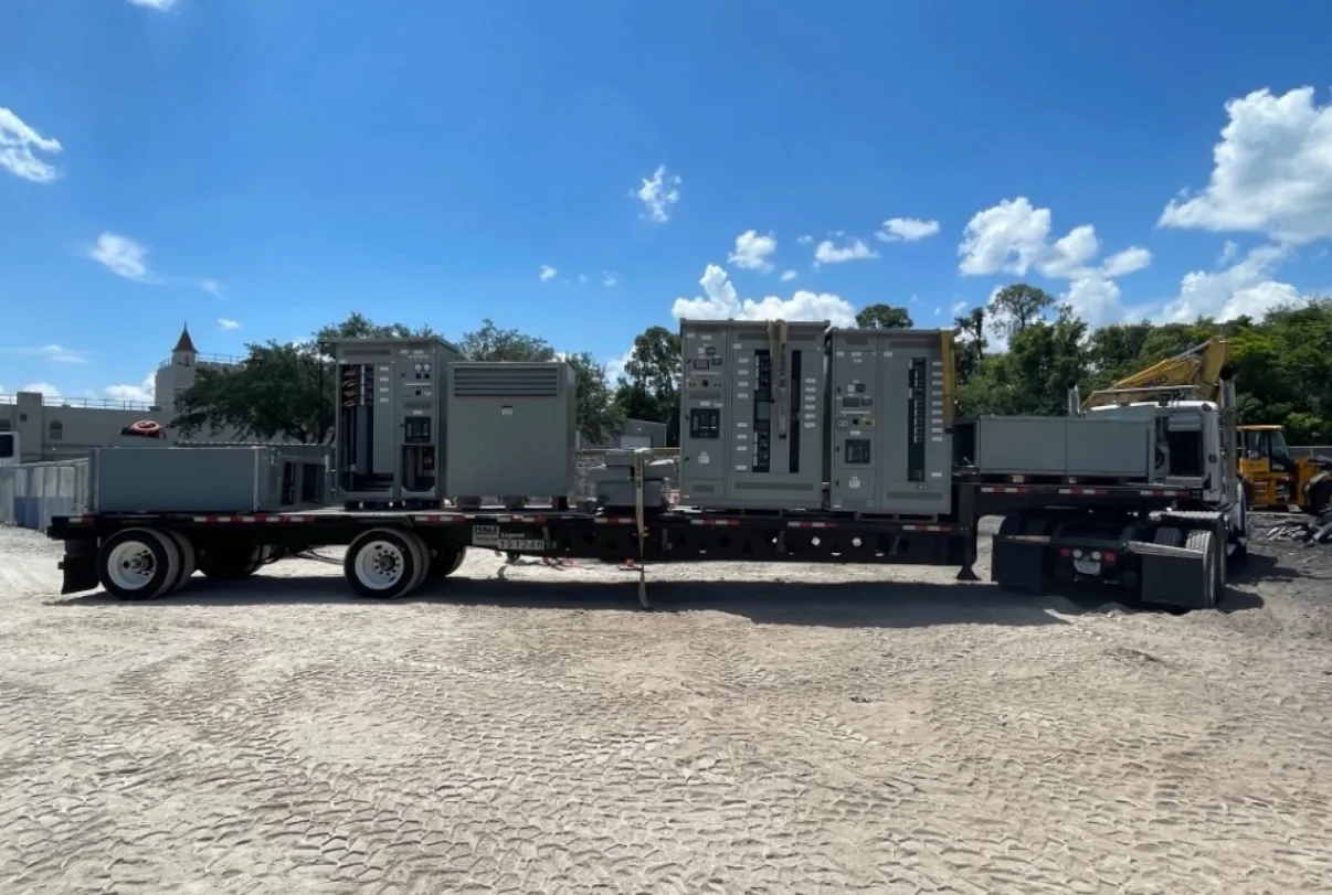
For a Lovelock delivery, coordinate the receiving point, unloading responsibility, access route, staging area, and sequence of delivery with the project team. These details can influence shipping configuration and installation planning, but no delivery date should be assumed until the order scope and logistics are confirmed. Confirm who is responsible for setting the equipment, making field connections, inspections, and commissioning; these responsibilities vary by project and contract.
Manufacturing Scope and Project Handoff
We manufacture new custom power-distribution equipment in the United States using all-American components, and ship nationwide, including to Nevada. Once the design inputs are reviewed, the equipment scope can be aligned with the required feeder lineup, ratings, construction, and project documentation. Short lead times are supported, but timing depends on the finalized requirements and order coordination.
Before release, the project team should reconcile drawings, breaker schedules, bus details, connection points, and installation constraints. Commissioning responsibilities and acceptance requirements should be agreed early among the owner, electrical contractor, engineer, and other designated parties. This handoff helps ensure the specified low-voltage switchgear is evaluated in the context of the actual Lovelock facility and its electrical system.