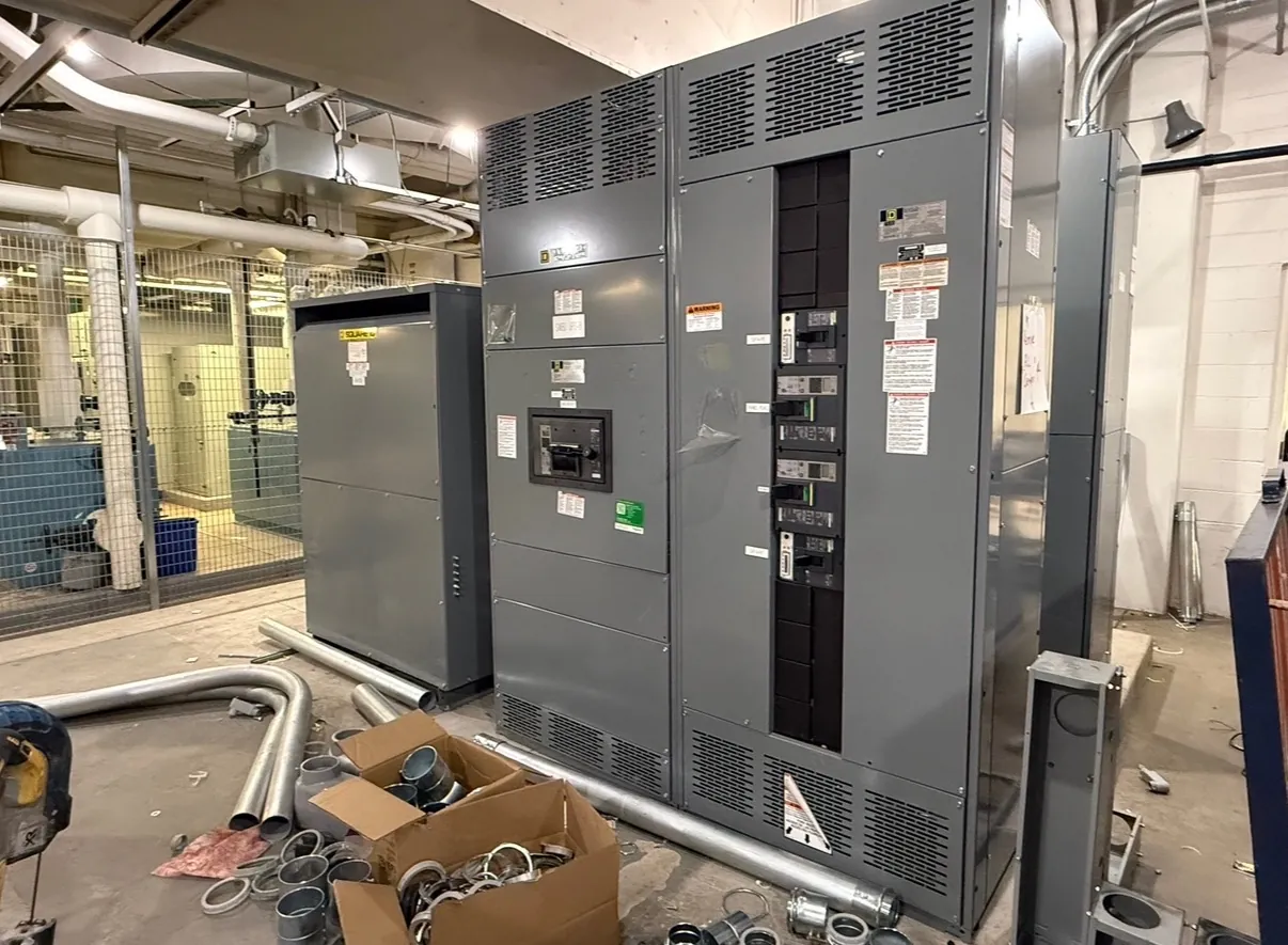
Power plant switchgear planning for Gardnerville projects
Power plant distribution equipment has to fit the generating equipment, connected loads and intended operating modes—not just a nominal system voltage. For a Gardnerville project, early design review should establish how generators connect to the plant distribution system, which loads must remain available during transitions, and where power can flow under normal, standby or maintenance conditions. These details shape the switchgear lineup, protective-device interfaces and the information needed for a useful quotation.
We manufacture new custom switchgear and power-distribution assemblies in the United States using all-American components, with nationwide shipping, including to Nevada. The equipment configuration is developed around project requirements; it should not be assumed that a standard lineup, rating or protective arrangement will suit every generating facility.
Generator connections, synchronization and operating modes — Power Plant Switchgear in Gardnerville, NV
Generator connections require coordination among the generator, its controls, the connected bus and the switching equipment. Project documents should identify whether generators operate independently, in parallel with one another, or in a configuration that can connect to another source. Synchronization functions and control responsibilities need to be defined by the project’s qualified electrical and controls engineers. Switchgear selection alone does not establish that a generator-paralleling scheme is appropriate.
Describe expected operating modes, including normal generation, startup, shutdown, standby operation and any planned transfer between sources. Note which breakers or other devices are expected to open or close in each mode, what interlocks or control interfaces are required, and whether operating sequences differ by unit. A clear sequence helps identify mismatches between the intended controls and the physical arrangement before fabrication details are finalized.
Protection, backfeed paths and source coordination
Protection depends on the complete power system, not a single device rating. Engineers need to evaluate available fault current, generator characteristics, grounding, conductor and bus data, protective-device settings, and coordination with upstream and downstream equipment. Identify every source that may energize a bus, including generators, utility connections, alternate feeds, and any other source shown in the one-line diagram. Backfeed conditions can change which equipment is energized and how protection must respond.
Share the latest one-line diagram, protection philosophy and device schedule when requesting a quotation. Where these are still under development, identify the open engineering decisions rather than assuming a protective scheme. Equipment ratings, listings and interfaces require confirmation against the final design and applicable project requirements.
Auxiliary loads and continuity priorities
Plant auxiliary loads can include controls, instrumentation, pumps, fans, lighting and other equipment needed for generation or facility operation. Their starting characteristics, required supply, criticality and preferred source may differ. Grouping loads by operating purpose can help the engineering team determine feeder arrangements and identify which loads should be shed, transferred or maintained during a change in operating mode.
For each feeder, provide the load description, electrical data available from the design, destination, and any special control or monitoring interface. Identify loads that must not be interrupted, loads that may be sequenced, and loads that depend on another system being available. These are design inputs, not assumptions that can be settled from a switchgear description alone.
Gardnerville site elevation, enclosure and environment
Installation conditions matter to equipment selection. Confirm the actual site elevation and have the responsible engineer review whether any equipment ratings or application limits need adjustment. Also specify indoor or outdoor placement, ambient conditions, exposure to dust or moisture, ventilation, corrosion concerns, and available clearances. These factors can affect enclosure construction, environmental features, equipment arrangement and installation planning.
Gardnerville delivery planning should account for the receiving location, access route, unloading arrangements and the path from delivery point to the equipment room or pad. Provide available layout drawings and note constraints such as door dimensions, turning space, floor or foundation conditions, and whether the lineup must be divided for movement. Shipping nationwide does not establish site access or installation readiness; those details need confirmation with the project team.
Information for a project-specific quotation — Power Plant Switchgear in Gardnerville, NV
Useful quotation inputs include the one-line diagram, system voltage, required equipment ratings, generator and source data, feeder schedule, fault-current and coordination information, operating sequences, control interfaces, enclosure and environmental requirements, and the project schedule. Include the intended installation elevation and the exact project location in Gardnerville. Flag assumptions and pending decisions so the scope can distinguish confirmed requirements from items needing engineering review.
UL 891 applies to applicable low-voltage switchboards; it should not be treated as a blanket standard for all switchgear or every product configuration. Any requested listing, rating or compliance requirement must be checked for the specific equipment and application. Final selection and system design require review by qualified electrical engineers familiar with the facility and site conditions.