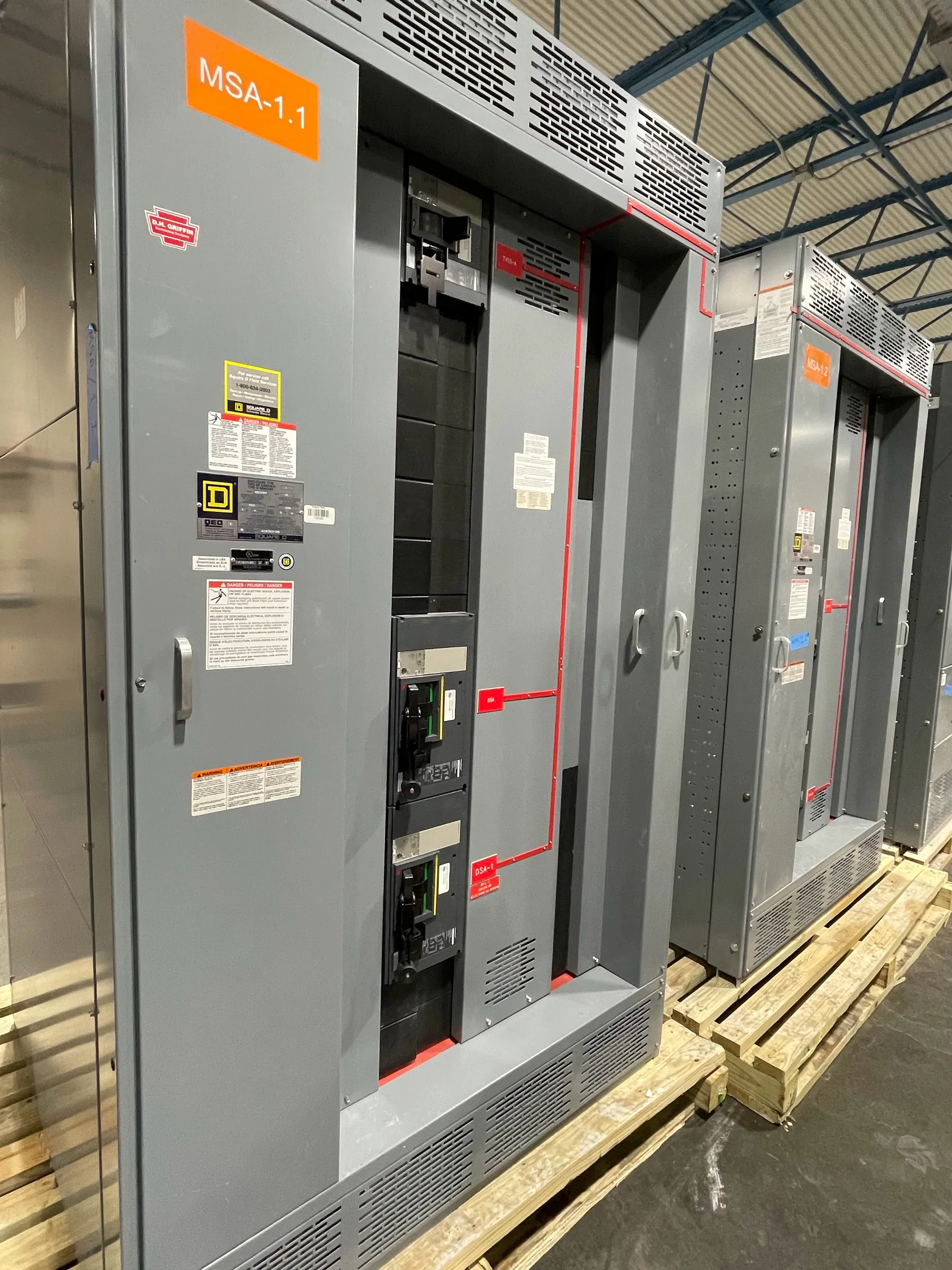
Power Plant Switchgear Planning for Fallon, Nevada
Power plant switchgear must fit the generating equipment, the electrical system it serves, and the plant’s operating plan. For a Fallon project, the design review should start with a clear account of how power enters, leaves, and moves through the facility—not simply a requested equipment name or nominal voltage. Generator connections, auxiliary distribution, protective devices, and possible backfeed paths all affect the assembly configuration. Our U.S. manufacturing business builds new custom switchgear and power-distribution equipment using all-American components, with nationwide shipping available for Nevada projects. Final equipment selection depends on qualified engineering review and confirmed site requirements.
Generator Connections, Synchronization, and Backfeed
Generator interconnection details shape the switchgear lineup. The engineering team needs to know whether generators operate independently, in parallel with one another, or in parallel with an external source, and which breakers provide each connection. Synchronization functions and controls must be coordinated with the generator controls and the broader protection scheme; switchgear alone does not establish a complete synchronization system. Review normal and alternate source arrangements, tie-breaker states, transfer sequences, and any conditions in which an energized source could feed back toward another part of the system. Documenting these modes helps identify the required interfaces and prevents assumptions about which devices may close together.
Auxiliary Loads, Motor Starting, and Load Profiles
Plant auxiliary loads can be significant to equipment selection even when they are not part of the generator output path. Pumps, fans, compressors, cooling equipment, and other motors may have different starting methods and operating sequences. Provide motor data, starting-current information where available, expected starting frequency, and any limits on voltage dip or simultaneous starting established by the project engineer. A load profile should distinguish continuous, intermittent, standby, and essential loads, and explain how those loads change during startup, shutdown, low-output operation, or a source outage. This information supports decisions about feeder arrangement, protective-device selection, and how distribution sections are separated.
Protection Objectives and Coordination Tradeoffs
Protective-device coordination is a project objective, not a setting that can be determined from a general equipment description. The engineer needs the available fault-current information, source and transformer data, generator characteristics, conductor details, and protective devices upstream and downstream. The coordination study can then assess which devices should respond to specified fault conditions and how selectivity, equipment protection, and clearing time interact. A preference for selective operation may require different device choices or settings than an objective focused on limiting equipment stress. These tradeoffs should be evaluated together by qualified engineers; ratings, device functions, and coordination assumptions require confirmation against the actual system and applicable project requirements.
Ratings, Construction, and Nevada Site Conditions
When preparing a switchgear specification, distinguish system voltage from equipment ratings. Confirm the intended system configuration, continuous-current needs, short-circuit requirements, enclosure conditions, incoming and outgoing cable arrangements, and any environmental constraints. Fallon-area logistics and facility conditions should be reviewed without assuming a particular site: access for freight and rigging, indoor or outdoor placement, dust exposure, temperature range, and available working space can influence enclosure and installation planning. UL 891 applies to applicable low-voltage switchboards; it should not be treated as a blanket listing for every switchgear assembly or for medium- or high-voltage equipment. Applicable standards, listings, and ratings must be verified for the specified product and application.
Information That Helps Define a Project Quotation
A useful quotation package gives the manufacturer enough detail to identify the required lineup and interfaces while leaving system decisions with the project’s qualified design team. Include single-line diagrams, equipment schedules, source and generator data, load lists, motor-starting requirements, control and communications needs, and stated protection objectives. Note known site constraints, preferred cable entry, future feeder provisions, and whether the plant has multiple operating modes. Identify which documents are preliminary and which are approved for equipment design. Missing or changing information can affect configuration and schedule, so assumptions and open items should be recorded before the design is finalized.
From Engineering Review to Equipment Delivery
After requirements are reviewed, the equipment configuration can be developed around the approved drawings, ratings, protective-device requirements, and connection details. This manufacturing approach is intended for new custom equipment rather than a brokered selection from unrelated stock. Short lead times are supported, but an exact schedule depends on the confirmed scope, component and design requirements, and project approvals; no delivery date should be assumed before those details are reviewed. Equipment can ship nationwide, including to Fallon, with shipping and site receiving arrangements coordinated to the project. Installation, system integration, and commissioning plans remain dependent on the facility design and responsible engineering team.