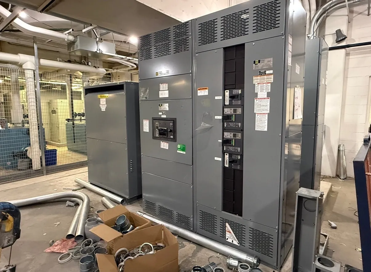
Metal-Clad Switchgear for Elko, NV Project Conditions
Metal-clad switchgear is a medium-voltage assembly designed with grounded metal barriers that separate major components, including the bus, circuit breakers and cable terminations. For an Elko-area project, the equipment specification should reflect the actual electrical system and the conditions where the lineup will be installed—not assumptions based on the city name. The project team should document system voltage, available fault current, grounding method, operating requirements and the intended indoor or outdoor location. A qualified electrical engineer must confirm the design and ratings against the one-line diagram, utility or facility requirements, and applicable codes.
Elko’s regional climate makes site-specific ambient and enclosure details important. The specification should state the expected temperature range, elevation, exposure to dust or moisture, ventilation conditions and any unusual environmental demands. Those inputs can affect enclosure construction, space heaters or other environmental provisions, equipment ratings and installation planning. Shipping to Nevada can be coordinated from a U.S. manufacturer, but transport and site access should be considered separately from the electrical design, including unloading arrangements, route constraints and the prepared switchgear room or pad.
Metal Barriers and Compartmentalized Construction
Compartmentalization helps organize the lineup and limit direct access between functional sections. The design may include separate compartments for the main bus, circuit breakers, instrument transformers and cable connections, with grounded barriers and shutters specified as appropriate to the equipment arrangement. These boundaries are a design feature, not a substitute for the manufacturer’s instructions, site safety program or qualified personnel.
Teams should review how the compartments relate to the one-line diagram and cable schedule. Incoming and outgoing cable locations, bus connections, metering, relaying and future provisions all influence the lineup arrangement. More barriers or distinct compartments can support separation objectives, while also affecting dimensions, cable access and maintenance procedures. The project drawings should make clear which components are included, where external control wiring enters, and how the assembly interfaces with transformers, generators, utility service or downstream equipment.
Withdrawable Breakers, Ratings and Interchangeability
Withdrawable circuit breakers allow a breaker to be moved between defined positions within its compartment, subject to the equipment design and manufacturer’s instructions. For a project, specify the breaker type and ratings required by the system study, along with the required operating and interlocking features. Consider whether the facility expects spare breakers, common breaker configurations across feeders, or a particular arrangement for testing and maintenance. Interchangeability should never be assumed: it depends on the switchgear design, breaker type, rating and specified construction.
Breaker interrupting and withstand ratings must be evaluated against system conditions, including available fault current and protective-device performance. Do not confuse a voltage rating with the nominal system voltage, or infer that a rating makes an assembly suitable for every installation. The engineer should confirm ratings, configurations and interfaces for each lineup section. If the project requires a specific listing or standard, identify it in the inquiry and verify its applicability to the proposed equipment.
Grounding, Protection and Relay Coordination — Metal-Clad Switchgear in Elko, NV
Grounding provisions should match the system grounding method and the project’s protection scheme. The specification may address the ground bus, connections to the site grounding network, cable grounding details and any required grounding provisions for individual sections. The engineer should review these elements with the one-line diagram and grounding study; requirements can differ between utility, industrial and institutional systems.
Relay coordination is a system-level task. Protective-device settings and curves should be evaluated with upstream and downstream devices, transformer characteristics, conductor limits and the facility’s fault-current study. The switchgear supplier can use project-approved relay and instrument-transformer requirements to configure the assembly, but coordination decisions require qualified engineering review. Provide relay functions, communication interfaces, metering needs, control power, trip and close circuit details, and any required integration with supervisory or plant-control systems. Confirm that drawings identify responsibility for settings, programming, field testing and final documentation.
IEEE C37.20.2 and Project-Specific Compliance
IEEE C37.20.2 is the relevant IEEE standard to identify when specifying metal-clad switchgear within its scope. The project documents should state the required edition or contract basis and clarify which lineup, compartments and ratings are expected to comply. The standard should not be treated as a blanket certification for every component or application. Applicable requirements depend on the equipment design and project specification, and the manufacturer should confirm the proposed configuration against the requested standard.
For low-voltage switchboards, UL 891 may be relevant, but it is not a standard for metal-clad medium-voltage switchgear. Product type and voltage class matter. Listings, certifications and utility acceptance must be confirmed for the specific equipment and project; none should be inferred from a general product description.
Elko Site Inputs for a Complete Equipment Quote
A useful quotation package includes the one-line diagram, system voltage, fault-current information, grounding method, feeder schedule, protection requirements and requested equipment ratings. Add the specified ambient conditions, enclosure requirements, room or pad dimensions, cable entry direction, aisle and maintenance access, conduit locations and transportation or unloading constraints. Maintenance access deserves early attention: breaker withdrawal space, door clearances, cable termination access and routes for moving equipment can affect room layout and lineup dimensions.
U.S.-built assemblies using all-American components can be configured for project requirements and shipped nationwide, with lead times dependent on the approved design, components and production schedule. Before release, the project team should review drawings, interfaces, ratings, standard requirements and site conditions with the manufacturer and qualified engineer. That review helps align the equipment with the actual Elko installation rather than relying on generic assumptions.