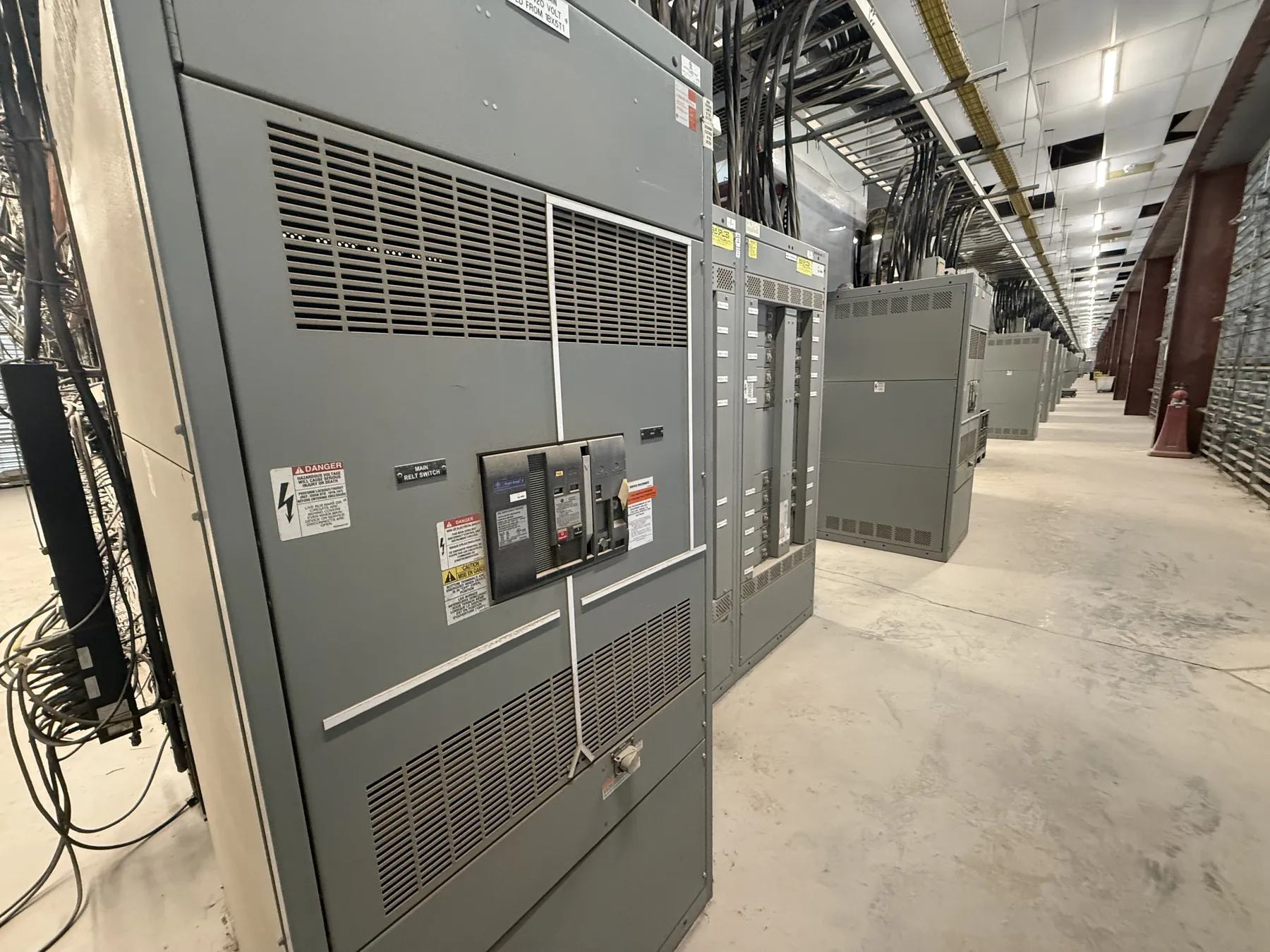
Industrial Switchgear for Elko Facilities
Industrial electrical distribution in Elko starts with the work a facility needs the system to perform. A process line with large motors, a building with mixed mechanical loads, and a site with future expansion plans can call for different switchboard arrangements, protective devices, and feeder provisions. A sound equipment specification connects the one-line diagram to actual operating duty, available fault current, environmental conditions, and the way staff will maintain the installation.
We manufacture new custom switchgear and power-distribution equipment in the United States using all-American components, with short lead times as a stated manufacturing objective and shipping available nationwide. For an Elko project, equipment details still need to be established from the project documents and site conditions; location alone does not determine a suitable design, rating, or delivery date.
Motor Starting and Variable-Frequency Drive Interfaces — Industrial Switchgear in Elko, NV
Motor starting can create current demands and voltage effects that differ from a motor’s normal running load. The specification should identify motor sizes, starting method, frequency of starts, operating sequence, and whether motors start together or in stages. Those details help the project engineer assess feeder loading, protective-device selection, and possible effects on other loads. A motor starter’s function and rating must be matched to the motor and application rather than inferred from the switchgear’s overall current rating.
Variable-frequency drives introduce additional interface questions. Confirm whether drives are supplied within the distribution assembly or by another vendor, and document their input requirements, protective-device recommendations, heat dissipation, and connection points. Drive enclosures and switchgear layouts must account for heat and cable routing. Coordination between the drive supplier, equipment manufacturer, electrical engineer, and installer can prevent mismatches in connection space, protection, or responsibility for drive-related components.
Load Duty, Fault Current, and Protective Coordination
Provide a current one-line diagram and load information that distinguish continuous loads, intermittent processes, standby or emergency sources, and planned spare capacity. A total connected-load figure by itself may not describe how the facility operates. Load duty affects feeder arrangements and equipment selection, while expected changes to production or building systems may influence the layout and reserved provisions.
Available fault current at the proposed equipment location is a separate design input from normal load. It depends on the source and the electrical system between that source and the switchgear. Protective devices must be selected and evaluated for the applicable voltage, current, and fault-duty requirements. Coordination studies should consider upstream and downstream devices, source configurations, and the project’s operating priorities. The engineer of record must confirm the study assumptions and final protective settings; a product quotation cannot establish those values without the relevant system data.
Equipment ratings describe particular capabilities and are not interchangeable with system voltage. Any proposed rating, applicable listing, and configuration require confirmation against the project specification and installation conditions. UL 891 applies to applicable low-voltage switchboards; it should not be read as a blanket standard for all switchgear or for medium- or high-voltage equipment.
Elko Site Conditions, Enclosures, and Access
Document the specified ambient conditions for the actual installation location, including the conditions expected in the electrical room or equipment area. Outdoor exposure, dust, moisture, temperature variation, corrosive substances, and nearby process heat can affect enclosure selection and equipment arrangement. State whether the assembly is indoors or outdoors and identify the environmental conditions the design must address. The project team should confirm the required enclosure characteristics and any applicable derating or installation constraints.
Maintenance access is also a physical design input. Provide room dimensions, door and aisle clearances, cable-entry direction, conduit locations, and any obstacles that could affect placement or future service. Confirm the intended access side and whether equipment must fit through existing openings. These details are especially important where a facility has restricted electrical-room space or operating processes that limit when installation work can occur.
Information for a Clear Equipment Quotation — Industrial Switchgear in Elko, NV
To develop a useful scope, share the project’s one-line diagram, equipment schedule, specifications, load and motor data, fault-current information, coordination requirements, and site layout. Include system voltage, requested equipment ratings, source and feeder arrangements, enclosure requirements, cable-entry preferences, and any defined interface with drives or other vendors. Identify applicable project documents and note which details are still pending engineering review.
For Elko delivery planning, provide the ship-to location, receiving constraints, access limitations, and requested project milestones. We ship nationwide, but transportation, site access, and project sequencing should be reviewed with the project team; no schedule should be assumed without confirmation. Clear inputs help distinguish confirmed requirements from open engineering questions before equipment configuration is finalized.
From Specification Review to Manufactured Equipment
Custom industrial distribution equipment must fit the electrical design and the physical installation, not merely a generic application label. During specification review, confirm the proposed arrangement against the approved drawings, device requirements, environmental conditions, and interfaces with other equipment. Changes to load duty, source configuration, fault-current assumptions, or room layout can affect the design and should be communicated before release for manufacture.
Our role is to manufacture new equipment to the confirmed project scope. Qualified engineers and the project team remain responsible for system design, code compliance, protective coordination, and site-specific decisions. Resolving those responsibilities early gives an Elko facility a clearer path from equipment requirements to an installation suited to its operating conditions.