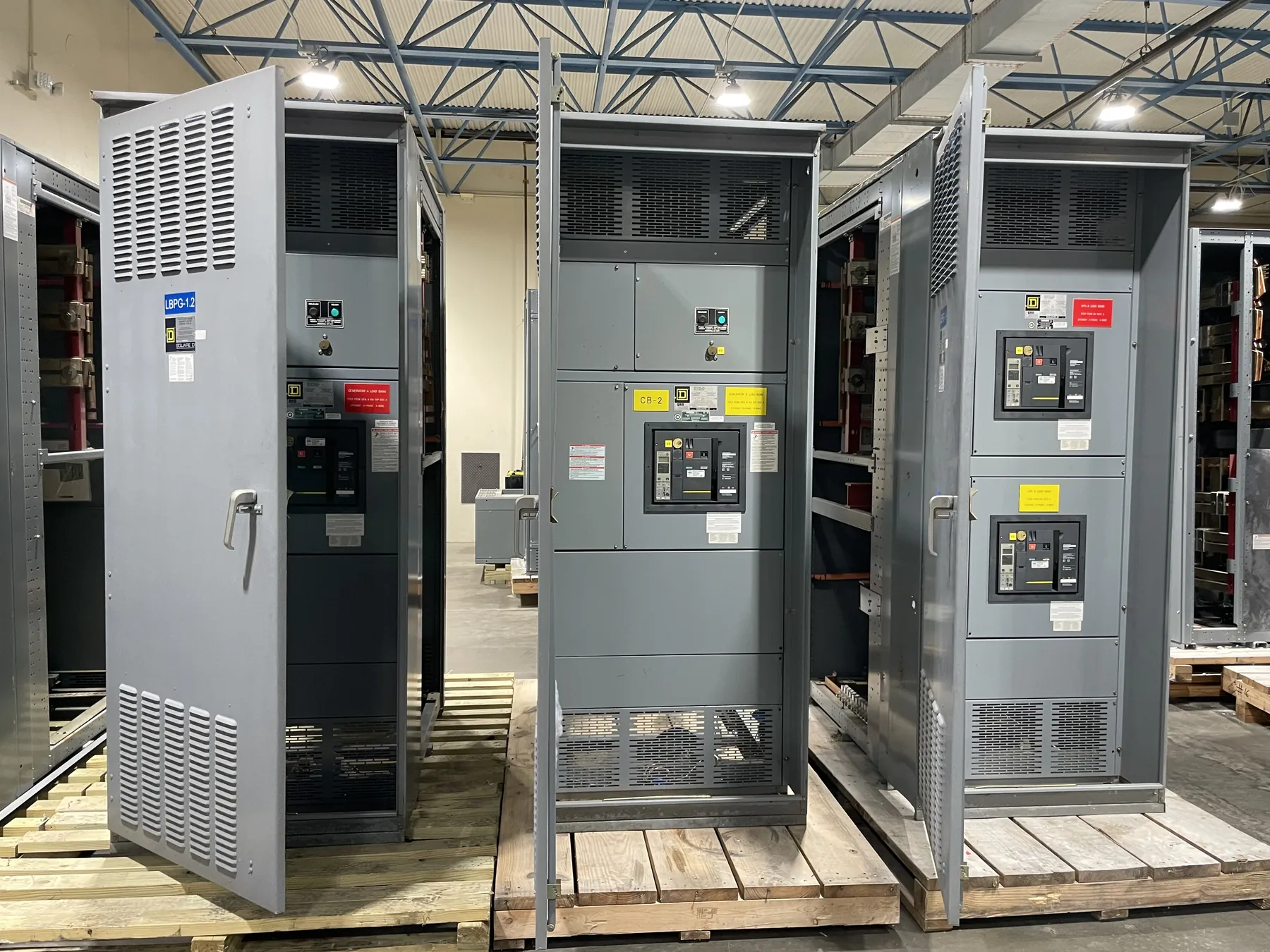
Airport Switchgear for Boulder City Operations
Electrical distribution at an airport must serve more than terminal lighting. Depending on the facility, loads may include runway and taxiway lighting, airfield signs, hangars, maintenance areas, communications, security systems, administrative spaces, and support buildings. Their operating priorities differ: some can tolerate a planned interruption, while others need a carefully coordinated transition between sources or distribution paths. For a Boulder City airport project, start by identifying each load, its location, operating schedule, and required continuity. That inventory gives the design team a basis for dividing circuits into practical groups and selecting switchgear suited to the actual service arrangement.
Custom switchgear and power-distribution equipment can be manufactured around documented project requirements rather than a generic airport configuration. The manufacturer builds new equipment using all-American components, with assemblies built in the USA and shipment available nationwide. Lead times may be short, but schedule expectations depend on confirmed design details, component requirements, approvals, and coordination with the project team.
Define the Utility, Metering, and Grounding Interfaces First
Before the service design is released, establish how the airport’s electrical system connects to the serving utility. The design team needs the utility’s service requirements, available system information, proposed service location, metering arrangement, and responsibility boundaries. Metering may affect enclosure layout, access, compartmentation, and the location of service equipment. Those details should be coordinated with the utility and project engineers rather than assumed from a general one-line diagram.
Grounding and bonding also require a site-specific design. The project team should document the service grounding arrangement, equipment bonding approach, and interfaces with building systems and any separately derived sources. Airport conditions such as multiple buildings, long distribution routes, outdoor equipment, and sensitive electronic systems can make coordination especially important. The applicable system voltage, equipment ratings, and construction details must be confirmed by qualified electrical professionals against project documents and site conditions.
Separate Critical Loads from Routine Distribution
Not every airport circuit needs the same level of continuity. Identify operationally critical loads—such as designated airfield lighting, communications, security, or other systems specified by the owner—and distinguish them from loads that can be interrupted during planned work. The airport operator, electrical engineer, and relevant system designers should establish which loads require emergency or standby power and how those sources are intended to connect.
That decision influences switchgear arrangement, feeder grouping, transfer equipment interfaces, and space for future circuits. A design that combines dissimilar loads without a clear operating rationale can complicate maintenance and outage planning. Conversely, separating every load into its own section may add complexity without improving the facility’s actual operating resilience. The right balance depends on the owner’s continuity objectives, source architecture, protection design, and the physical distribution plan.
Coordinate Emergency Sources and Phased Outages
Where generators or other emergency sources are part of the project, define their electrical and control interfaces early. The engineering team must determine which loads are served, how sources are selected or transferred, what interlocking and protection functions are required, and how the arrangement fits the approved system design. Switchgear should not be specified as though an emergency source can simply be connected without evaluating fault conditions, operating modes, and the complete distribution system.
Airport work may need to proceed in phases so unaffected areas remain in service. A phasing plan should identify equipment boundaries, temporary service needs, cutover points, and the periods when specific circuits can be unavailable. Construction access, airfield operating constraints, security controls, and coordination with airport personnel may affect delivery, staging, and installation windows. These conditions are project inputs, not assumptions to resolve after equipment is released.
Choose Ratings and Construction from Project Data
Specify equipment from the documented service conditions and design—not from voltage alone. Relevant inputs include system voltage, continuous load requirements, available fault-current information, protective-device coordination, enclosure environment, feeder count, cable entry, and future expansion needs. A switchboard’s current or interrupting rating is not the same thing as system voltage; each value must be selected and verified for its intended application.
UL 891 applies to low-voltage switchboards when the applicable product and configuration meet the relevant requirements. It should not be treated as a blanket standard for all switchgear or as coverage for medium- or high-voltage equipment. Listings, ratings, and product applicability must be confirmed for the specific assembly and project. Qualified engineers should review the one-line diagram, equipment schedules, utility information, and site conditions before design approval.
Prepare a Complete Boulder City Quotation Package — Airport Switchgear in Boulder City, NV
A useful quotation request includes the current one-line diagram, load and feeder schedules, utility service criteria, metering requirements, grounding details, source and transfer scheme, fault-current data, enclosure location, and any applicable listing or specification requirements. Include the project sequence, expected review milestones, delivery destination, and known access or staging constraints. If details remain unresolved, identify them explicitly so they can be coordinated before fabrication is authorized.
This information helps align the manufactured assembly with airport operations and the project’s electrical design. Once the interfaces, ratings, and construction requirements are confirmed, the manufacturer can develop a proposal for new custom equipment and coordinate the production schedule with the project team.