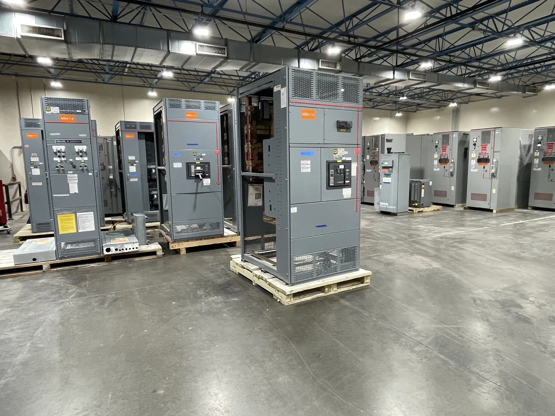
Power Plant Switchgear for Lovelock, Nevada Projects
Power plant distribution has to reflect how generation connects to the facility, how plant loads are supplied, and what happens as operating conditions change. For a Lovelock project, those questions should shape the switchgear scope before equipment is specified or quoted. A custom assembly can be configured around the project’s documented distribution requirements, but its ratings, construction, applicable listings and interfaces must be confirmed by qualified engineers against the one-line diagram, site conditions and governing requirements.
We manufacture new custom switchgear and power-distribution equipment in the United States using all-American components. Equipment can ship nationwide, including to Nevada. Delivery planning is project-specific: access, unloading arrangements, receiving hours, storage conditions and the sequence of construction all affect how equipment should be packaged and handled. Early coordination helps avoid treating transportation as an afterthought.
Define Generator Connections and System Boundaries
Start by identifying each generator connection point and the boundary between generator equipment, plant switchgear and downstream distribution. The electrical design should establish the system voltage, available fault current, grounding approach, conductor arrangement and required interruption or withstand ratings. A rating is not interchangeable with system voltage; both must be checked, along with the equipment’s specific application and configuration.
Generator output may connect to a common bus, separate sections, or another project-specific arrangement. The choice affects bus segmentation, feeder counts, isolation points and the consequences of taking a section out of service. Where multiple sources can feed a bus, the design also needs to account for the contribution from each source under relevant operating conditions. These determinations belong in the engineering design, not in a product description alone.
Coordinate Protection, Synchronization and Backfeed
Protection and synchronization depend on the generation scheme and the controls and protective devices provided elsewhere in the system. Confirm which equipment detects abnormal conditions, which devices initiate trips, and how the switchgear’s breakers and control interfaces participate. Synchronizing functions may be located in separate control systems; their signals, interlocks and responsibilities should be identified clearly so that the switchgear package is neither assumed to provide functions outside its scope nor left with undefined connections.
Backfeed can occur when more than one source is connected or when an operating mode changes the direction or path of power. Engineers should review normal, startup, shutdown, maintenance and contingency arrangements, including any tie breakers and alternate feeds. The resulting protection coordination and operating philosophy influence breaker selection, compartment arrangements, controls and labeling. Final settings and operating procedures require qualified engineering review for the actual installation.
Account for Auxiliary Loads and Operating Modes
Plant auxiliaries can be essential to generation, even when they do not connect directly to the generator output. Build an equipment schedule that identifies major motors, transformers, control-power needs and other loads supplied from the distribution system. Starting characteristics, load criticality and expected simultaneous operation may affect feeder assignments and the division of loads among bus sections. The design team should determine which loads need alternate sources and how transfers or load shedding are intended to work.
Operating modes deserve equal attention. A plant may have different configurations during normal generation, startup, shutdown, standby or maintenance. Document which sources and ties are available in each mode, what equipment must remain energized, and whether any loads can be interrupted. This information helps define feeder quantities and control interfaces while giving commissioning teams a clear basis for functional checks. It also reduces the risk that a quoted arrangement silently assumes a single operating condition.
Provide the Inputs Needed for a Useful Quote
A practical quotation package should include the current one-line diagram, system voltage, required ratings, source and feeder schedule, anticipated fault-current information, grounding details, control and metering requirements, and any project specifications. Identify the quantity and type of incoming, generator, tie and outgoing feeders, as well as spare or future provisions. Provide known room dimensions, cable-entry direction, access limitations and environmental conditions so enclosure and connection details can be reviewed.
Applicable product standards and listings must be confirmed for the specific equipment and configuration. UL 891 applies to applicable low-voltage switchboards; it should not be treated as a blanket designation for every switchgear assembly or for medium- or high-voltage equipment. The project engineer should confirm the required product category, ratings and approval path before procurement.
Plan Delivery and Commissioning Responsibilities Early
For Lovelock facilities, discuss delivery handling while the equipment scope is being developed. Confirm the receiving location, truck access, unloading method, laydown area, protection from weather and dust, and whether the equipment can be moved from the delivery point to its final room without obstruction. Site-specific conditions should be verified by the project team rather than assumed from the city name. Shipping schedules and packaging needs also depend on the confirmed order and destination.
Set commissioning boundaries among the manufacturer, electrical contractor, controls integrator, generator supplier and owner’s engineering team. Document who provides field connections, control wiring, settings, system integration checks and final acceptance activities. Custom switchgear is manufactured to an agreed scope; successful integration still depends on complete project information, coordinated interfaces and qualified review of the installed system.